
I got intrigued with the idea of catching a fish from an RC boat. Wouldn't it be fun to sit on the dock and see a trout hit your line, then try to land the fish? As with many projects, this one expanded a little more than I figured it might, but it is fun to learn about RC modeling. and try a few things I've never done before. Probably some of the things I've done on the boat haven't been done by anyone before, they have more sense.
Since I'd never done a project like this before. I'll try to write it up as I go so I don't forget things. I don't really know who might enjoy reading this. It combines some things about remote control, collecting and fabricating some parts, and designing the electronics to make these things play together. I suppose most of the unique things are with the electronics stuff. There's no rocket-science here, but if you aren't used to electronics, some of it will probably be kind of boring to you. Well, might be boring even if you if are used to electronics, but I'll write it up anyway - it might give you a few ideas for your own projects or help prevent you from making some of the mistakes that I did along the way, which I have included.
In the rare chance that you do find something interesting here, and want more details, let me know. I'd be happy to share parts drawings, microprocessor code, or schematics with you.
This write-up has turned out to be a lot longer than I thought (just like the project), so while it is all below in some sort of chronological order, you can go straight to each section from here if you wish...
Finding a Hull
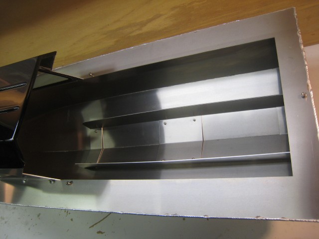
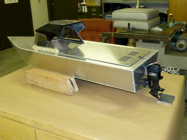
I'm not one of those enviable people with endless skill and patience, so when I saw a boat hull for sale on CraigsList, I decided to see if it would work for this purpose. A father/son team just south of Seattle makes these hulls from CNC-cut 5052-aluminum sheets, then TIG-weld them together. My hull is 49" long, which gives you quite a bit of buoyancy in the case of a larger trout hitting the line. At the time I bought mine, they had some prototypes that were selling for about $200, a very fair price. Here's what the hull looks like when you get it...
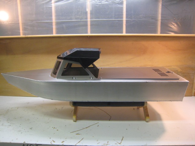
There's a cover over the rear part of the hull...
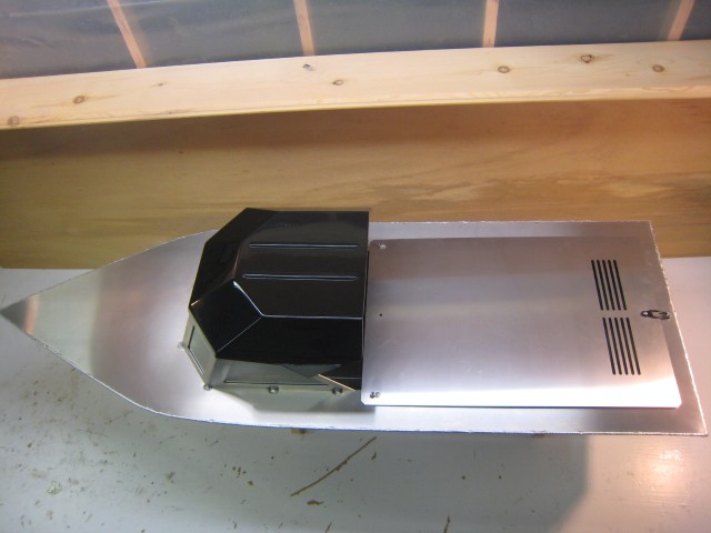
And a strengthening rib inside...
If you're interested in learning more about these hulls, here's contact information...
I'm not sure what scale it is supposed to be, but I'm guessing that the design represents about a 24' boat, and that makes it about 1/6 scale.
It's time to start converting this to a fishing machine!
I figured that if you are going to efficiently land fish, it would be a big help to be able to reel your line in and out via remote control. I decided that maybe I could convert an old salmon-fishing reel (Penn 209M) for the task.
I decided to use a 6V sealed lead-acid battery in the boat, the type used as backups in alarm systems. This sets the stage for finding an appropriate motor and electronic speed control (ESC). My brother gave me an M.troniks 600 marine motor that didn't work out on his project - it was too fast, but I figured that it could be made to work for the reel with the correct gear ratio.
With a reel, you want to be able wind it in or out, but not let a fish pull it out - that's what the drag is for on the reel. But I couldn't leave the "clicker" in place on the reel since it would prevent me from using the motor to run out line, it makes the reel handle a one-way device. So I decided that I needed a worm-gear setup. Worm gears don't allow the big gear to turn the "worm," but the worm can drive the big gear either way.
I found a worm-gear set from Servo City, but the driven gear wasn't appropriate for this task, so I decided to try to make one on my milling machine. The guys at Servo City gave me the pitch and angle of the worm gear, so I used that information in Excel to compute all the XY moves necessary. Lots of sines and cosines and head scratching involved, then writing a little program to convert that to G-code. The gear center (which fits where the handle used to be on the reel) needed to be an oval shape to match the reel. Penn uses a really odd screw that holds on the handle - it's 1/4"-32 threads per inch (TPI). I hadn't seen that before, usually fine pitch in 1/4" size is 28 TPI. While I couldn't find a screw in this thread anywhere, I did find a die and used that to make a screw with the appropriate threads.
Here's the milling machine working away on a scrap of Delrin to make the gear, I used a 1/16" cutter...
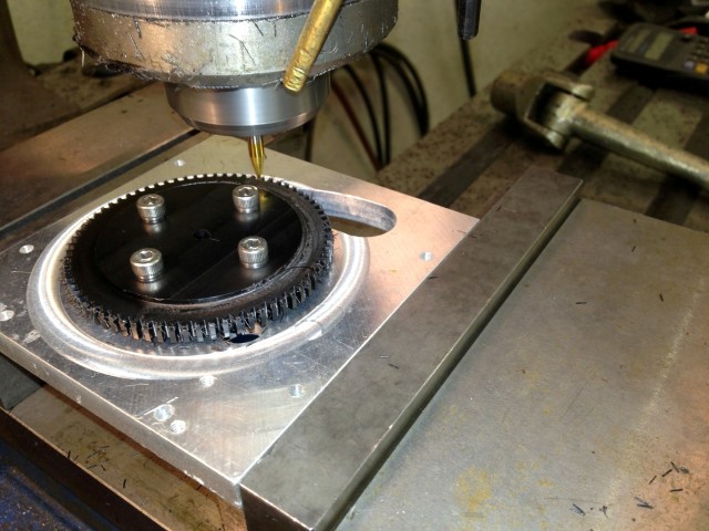
Since I made the gear, I found out about a really great software product for designing gears. Watch the "Demonstration Video" on this site, it's really impressive.... Gear Design Software
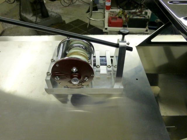
I made the rod holder so that it would hold a fishing rod at a twenty degree angle, and just used the end section of a break-down rod for the entire pole on the Fishing Machine. It is held in place with a thumb-screw, and since the rod-tip is hollow, I epoxied in a little steel rod at end so that it wouldn't collapse from the thumb screw.
Here's the reel/rod-holder from the starboard size...
From the front port side...
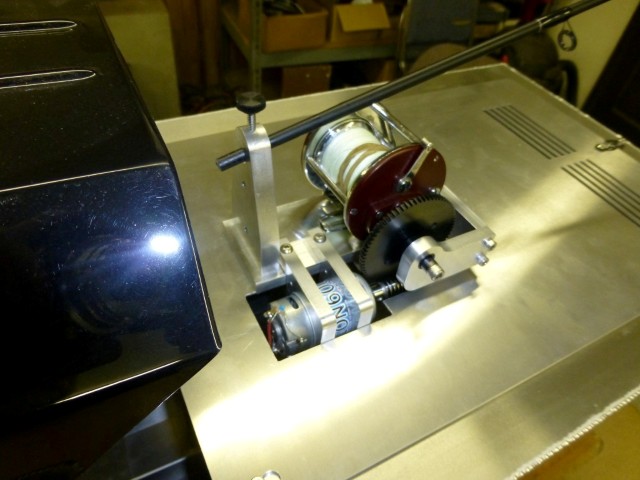
And here from the rear port side. I made an outboard bushing from Delrin to help support the gear-shaft...
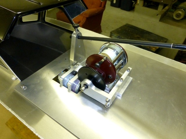
It works smoothly, and at about the right speed.
Originally, I figured that I would use an electric outboard motor. I found a vintage Robbe Roqua motor on eBay and bought that. It sounded to be about the right size - 9" high, which in 1:6 scale would make it about 4 1/2 feet high - seemed reasonable. When I tried it on the boat though, it looked too small. And in addition, there was little distance from the waterline to the top of the motor, so it could easily be submerged. Here's what it looked like...
The motor has since moved on for use on a boat designed and built by my brother to fit it. Great use for it on a boat built by a craftsman such as him.
For the next offering, I decided to see if I could find some bevel gears, and make my own drive units. I bought a couple cheap 380-sized electric motors, and some bevel gears that would normally be used in the differential of a Traxxas vehicle. I thought that maybe I could make the motors as in-board units, with the "screws" under the boat to help prevent line tangling. Speaking of that, a tug-boat man told me that they called the screws the "under water winches" since they got tangled so often. I bought brass 2" diameter propellers, one in LH pitch, and the other in RH. They are mounted with #10-32 threads, and have a 2" pitch. The pitch represents how for forward you would move with one revolution. By my calculation, that would make the boat move at 3 MPH if they were turning 1,580 RPM.
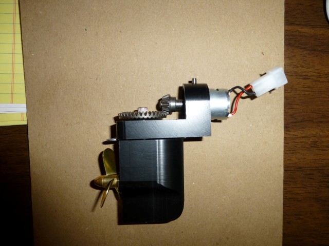
Here's my first prototype for the motor assembly, still in "block" form since I'm not worried about how they will work in the water yet, just if they will work at all. The hull would be sandwiched in-between the top block and bottom block.
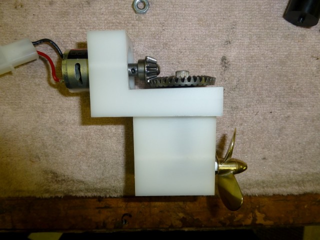
This is what is inside. The top bevel gears provide the gear reduction, and the bottom bevel gears work just like those in real outboard motors. The thick looking shaft is a Delrin bushing around an aluminum drive-shaft. It took a little thought about how to fabricate these since they had to be relatively water-tight, and you need to be able to assemble them.
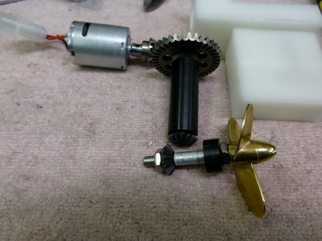
It was necessary to drill and tap the bevel gears at the bottom of the drive unit. I went through a couple of drill bits before I realized that the gears were well-hardened. I had to soften them (the real term is "anneal") by heating to red hot, then slowly cooling them in order to do the machining. When I was done, I re hardened them by again heating to red hot, then dipping them into cold oil. All this seemed to work fine. Well, except that they started a fire once they hit the oil. But it was pretty easy to get out. If there are liquids around, I usually have problems.
So I decided to go ahead with this design, and made a couple of these drive units with a little more finesse. I used black Delrin and stainless when practical so it wouldn't rust up. The little washer you see above the prop is serving as a spacer that represents the thickness of the hull (.062").
Once installed, this is what it looks like from inside the boat. I put some grease on top and in the bottom to lubricate things, slow down leaking, and to quiet it down. Still pretty noisy though from the metal gears.
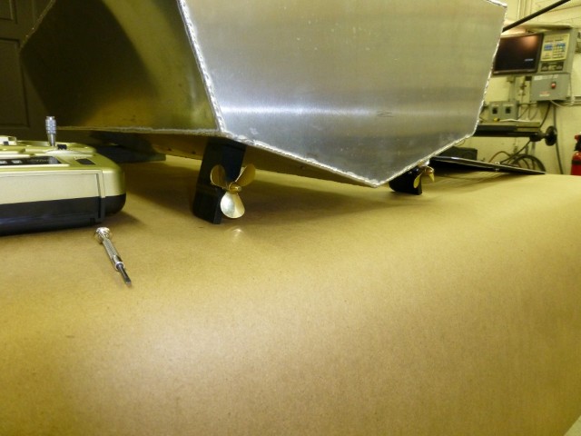
And this is what it looks like from the water side...
I decided to use two more of the Traxxas electronic speed controls (ESCs) for the drive motors, that way everything matches. Temporarily, I mounted all three ESCs (for the two drive motors and the reel) in the hull. These are nice ESCs, you can adjust them for zero-offset and gain.
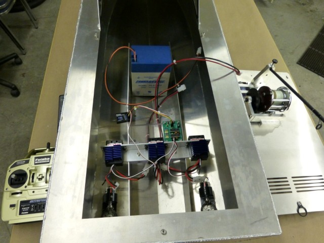
You can see the Futaba Controller that I purchased for this project. It's a relatively inexpensive 2.4 GHz unit with four channels, originally built for an RC airplane. One of the controls commands the reel, and the other controls the throttle and steering.
Well, now it can theoretically motivate - but how are we going to steer it? Standard practice would be to install a rudder behind each propeller, and operate them with a servo. I started thinking about a full-sized twin-screw inboard power boat that I once had the privilege to run. When docking and maneuvering in tight spaces, I found it easier to run by using the individual throttles and gear-shifts rather than the rudders. It could almost spin in its own length by doing this. I wonder if I could do the same with this boat? I decided to give a shot at making the joy-stick on the transmitter control the boat in this fashion.
I found out that the receiver that is commonly used in RC equipment generates a pulse-width modulated signal that is sent to the ESC or servo. If it has a 1.5 mSec pulse width, that drives the motor (via the ESC) or servo off. Then, if the pulse width goes to 1 mSec, that means one extreme of motor speed/direction, and 2 mSec is the other extreme. This happens at about a 50 Hz rate. The signals in this case, with the Futaba receiver and Traxxas ESCs were 3.3V in amplitude.
It's fun to tinker with PIC micro processors, so I decided to see if I could use one to read the turn and amplitude signals from the Futaba receiver, mess with them, and then send the "messed with" signals to the motors. The goal would be to have both motors run at the speed and direction indicated with fore/aft movement of the joystick, then if you turn, start decreasing the power to the motor in the turn direction. The more you move the stick sideways, the slower the inner motor goes - if you go more than half-way, the inside motor fully stops, then starts to move in reverse for an even faster turn. As a special case, if you move the stick sideways at less than five per cent throttle, it starts accelerating the motors equally, but in opposite directions.
I found that I could use a bunch of interrupts in the PIC to do this. Each of the input signals from the Futaba receiver uses an interrupt to the processor in conjunction with a counter that measures the pulse width in counts. Once the signals are measured, you can calculate what you want for output signals, then use two more interrupts for generating those. That poor PIC is really busy - even more interrupts are used for overflow of the counters, and doing math takes a lot of processor time too.
As it turned out, it was more than I could get one PIC to handle. It was so busy that the output pulses varied a little in time so the motors would jump once in a while while they were supposed to be off. To fix this, I tried an approach with two microprocessors. One is reading the inputs, and the other is doing the math and controlling the outputs. Meanwhile parallel data is passed between them via eight data lines. It works! I might have been able to make the single-controller work with a faster clock speed (I was only using 8 MHz) in conjunction with more optimized code, but I don't like it when things are this close to the edge.
Here's my debugging set-up. I made a temporary stand for the two motors so I could tinker with it on my bench. You see the two ESCs in blue, and my hot-rod dual-processor circuit in green.
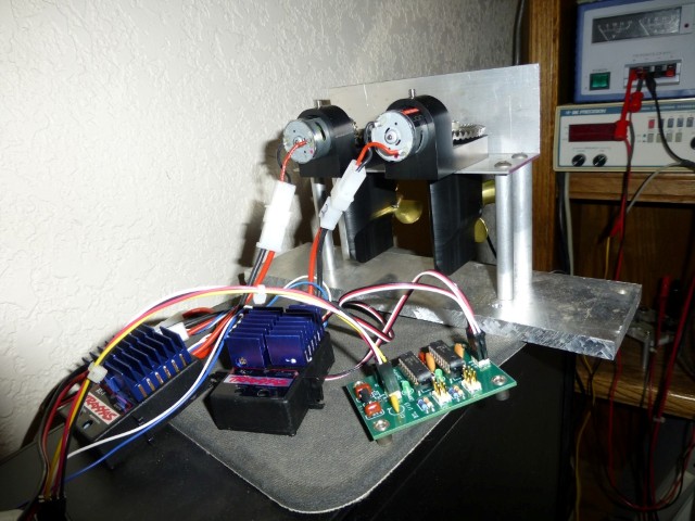
When I do projects like this, I use ExpressPCB to make printed circuit boards (PCBs). You lay them out with the free on-line software, then a few days later you get back three circuit boards for about $75. Makes it way more fun to build stuff like this when you roll your own Heathkit rather than dealing with a myriad of clip-leads, perf-boards and white-wires. The PCBs for this bargain price are fixed in size to be 3.8"x2.5", so often you can put two or more small PCBs on one layout, then cut them out.
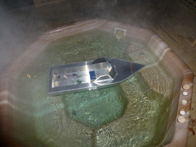
Time for a sea-trial in the hot-tub. Looks like the moors of England with fog rising - but it proves that the steering theory works!
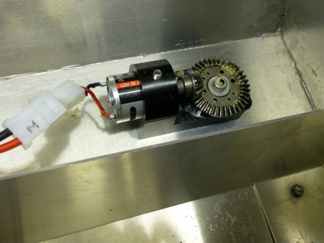
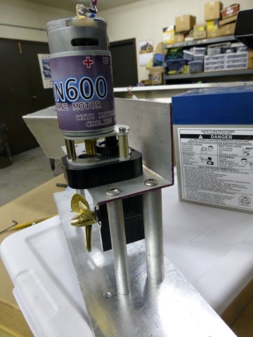
After fiddling around a little with the boat, I decided that the drive setup was too noisy, so went on to my third-offering of propulsion. I found a pair of gear-reduction units at a swap-meet that are used for propellers on RC planes. The small gear is brass, and the large gear is some sort of plastic - should be quieter than the metal gears I used previously. I used the same lower-units, and redid the top with these gear reductions and larger motors (600 sized), same as used on the reel.
While on the test stand (as shown) they were significantly quieter than before - things are looking up! But, when I mounted them in the hull, they got noisier. Still better than the original offering, but I guess this is just an artifact of mounting mechanical things in an aluminum hull that isn't very thick (1/16").
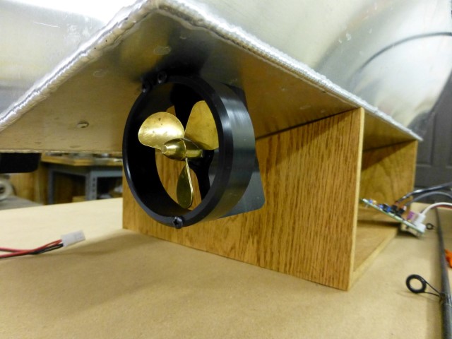
Meanwhile, my brother suggested that the line might get easily tangled in the props, so maybe prop-guards would be a good idea. So I machined up a couple from Delrin and added them to the out-drives. Here's what one of them looks like...
Now that the boat can do basic functions, like reel line in and out, float, travel and steer, I decided to see if I could make it a more capable fishing machine. After all, it's still winter in Seattle and what else are you going to do? I began to ponder the idea of sending data from the fishing machine back to the fisherman. Who hopefully will be me, sitting on the dock, enjoying a beer while sitting in a comfy chair.
If you can reel in and out, I can see the potential that you could easily lose track of how much line you have out. My first thought was to mount a sensor on the Delrin gear I made to drive the reel, but then I realized that the line can still go out when the gear is still, because of the drag. The only way to do it is to measure turns of the spool in the reel.
How about a Hall-effect sensor in the reel with a magnet fastened to the spool? Maybe there's room in there for that. But once you have a sensor that can tell when a revolution occurs, how do you know what direction it is going? If you have two sensors in the reel, that doesn't necessarily help - you can tell if it reverses direction since it will go past the same sensor twice in a row, but you don't know what direction you are going when you start, and even if you did, if you lose track, all future readings will be wrong. If the spool was a reasonably constant speed, and you had the sensors mounted at some angle other than 180 degrees apart, you could find the direction from the time between the two pulses, but that isn't the case here since the speed could be anywhere from zero to hopefully a high speed when the big one hits and drags out line. I decided that maybe I could put two sensors very close to one another so that both could be energized by the magnet at the same time, but sequentially. That way, if you sense when one gets triggered, you can see if the other is also triggered and hence know the direction. In one direction only one sensor would be triggered, but in the other, both would be triggered.
Well, lets see if we can make this work. These Hall sensors are little guys, and I have bad fine-motor-skills, but it's worth a shot. I made a little Lexan plate that should fit inside the reel, with holes for the leads from the sensors. Then super-glued the sensors in place.
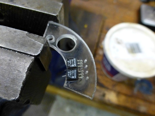
Once inside the reel, it looks like this. The wires run out the back of the reel side. In case you're interested, and haven't had a reel like this apart, the white plastic gear runs the level-line assembly (the guide that moves back and forth to make the line wind in evenly), and the brass ring is the spring that centers and holds the "clicker", which is the piece that looks like an arrow. That may not be the correct technical term, but you know what I mean.
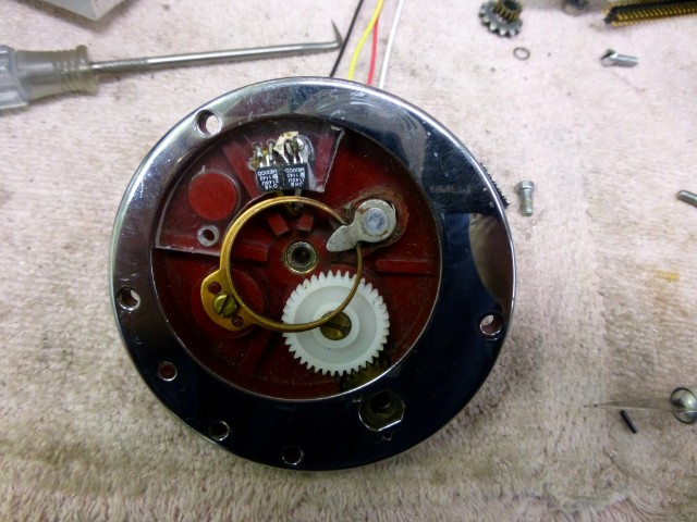
Finally, I epoxied a really strong magnet to the spool.
It's a rare-earth magnet. I ordered a sampling of these from a supplier a few years back for another project. When the box arrived, it was empty with a rip in the side. Evidently, the magnets were so strong, they were attracted to some of the post-office machinery and ripped a hole in the side of the box to stay right there. Fun to think about what might have happened to them over time. Maybe they are still there. Or maybe they caused mega buck damage to the machinery.
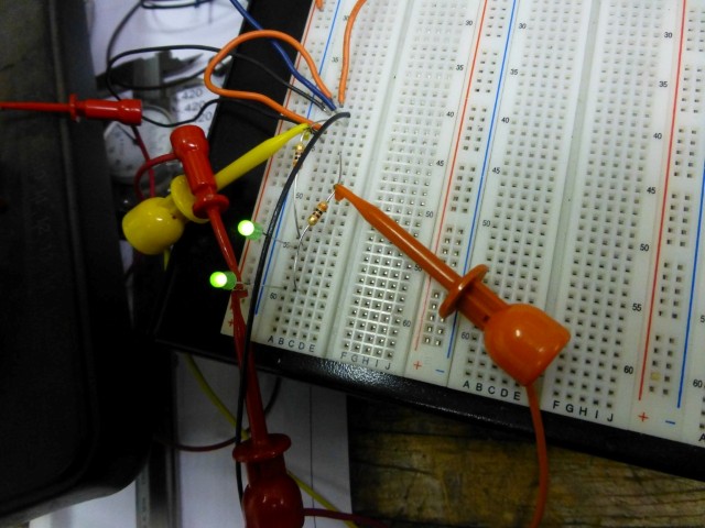
But, back to the fishing machine. I'll hook up a couple LEDs and see what happens. Going one direction, after waiting for the bottom LED to illuminate, I see this...
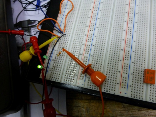
And going the other direction until the same LED illuminates, l see this. Success!
Of course this is going to necessitate another PIC micro-processor. The boat might start to resemble a computer inside, but that's what makes projects like this fun. I connected the first Hall-effect sensor to an interrupt in the computer. When the interrupt occurs, I read the second Hall-Effect sensor, and depending on it's state, either increment or decrement the count.
You're probably thinking that the diameter of the spool changes based on how much line you have out, so it won't be accurate. And you're probably right, but it should be close. I decided that I'll put enough line on the spool so that it's 1-1/4" diameter. That way the circumference will be about four inches (pi*d), so three turns will compute to be a foot of line in or out.
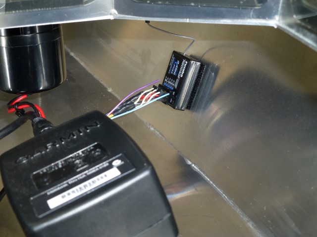
At this point, we have a microprocessor in the boat that can keep track of how much line we have out. That begs the question, how deep is the water? I decided that I would see if I could get also a report on water depth as I sip my brew on the dock. In a perfect world, a transducer that could make readings through the hull would be ideal, but these all seemed to be designed for wood or fiberglass boats rather than aluminum hulls. Well, there was one I found that was designed for a metal hull, but it was price-prohibitive. Poking around on eBay, I found that Garmin makes a through-hull depth sensor that is compatible with NMEA-0183. I ordered it to see if I establish communications with the microprocessor to read the data.
NMEA-0183 is a data convention used in boats that want to share data between devices. For example, you might have a compass that can share it's data with both a GPS system and an auto-pilot. It's basically a 4800-baud RS-232 data stream that goes between device. Recently, NMEA-0183 has been largely superceded by NMEA-2000, which is more like the CAN protocol used in modern cars. Most marine devices have been designed to read both protocols. I was happy to find the older standard for this use though, much simpler, although I would like to do a CAN-bus project someday, seems like you could do some interesting stuff with it.
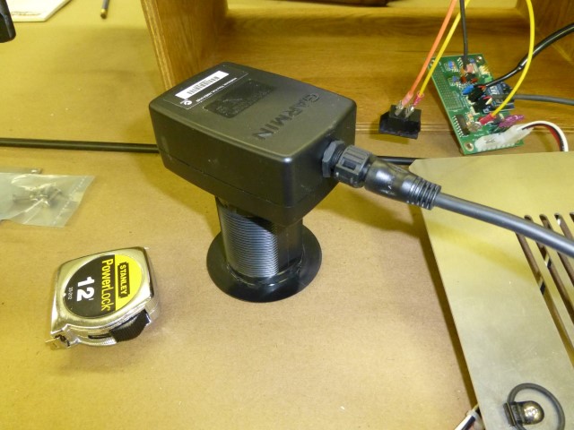
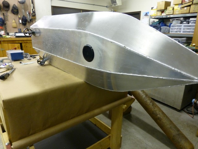
Here's what the transducer looks like. It's going to require a 2" hole in the hull for installation. Scary!
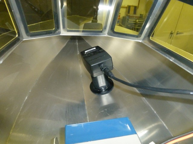
It looks like a good place to put it is up in the bow of the boat. There's quite an angle there, but these transducers come in two angles. The higher angle one is right for the 16 degree dead-rise of this hull. In the foreground (blue/gray) is one of the batteries. I haven't permanently located them yet. I want to get all the larger items done before I do most of the drilling in the hull. Before that, I will need to move the batteries around until it floats about level.
The depth transducer only takes three wires to hook up. Power, ground and the data signal line. Unfortunately, it wants 12V rather than the 6V which I had planned to use in the fishing machine. So I decided to use two six volt batteries, with the motors coming from the center-tap, and the depth-sounder coming from the series combination. It uses about 250mA. I wired another connection to the PIC for the incoming data line. It is a 3.3V digital signal from the Garmin transducer, so I used a pull-up to +5V to connect it to the PIC. From there, it's just a matter of reading the ASCII data. The transducer sends a header, for example "$SDDPT," followed by the depth, some other fields and terminated with a carriage return character. On my first sea-trial, I found out that the depth data I was using was meters rather than feet. Ed's pond really is deeper than 3'! By about triple.
As it turns out, the transducer also sends water temperature, so I got a free feature. To get the temperature, it's just necessary to wait for a "$SDMTW" header followed by the temperature. It's in Centigrade, so it needs to be converted to Fahrenheit for those of us used to that system.
We're starting to have quite a bit going on in the boat, so I'm thinking that maybe it would be a good idea to also monitor how our two six-volt batteries are doing in the boat. Luckily, I'm using a PIC 18LF1320 which has an A/D converter built in, so I wired in two voltage dividers, one with a 1:3 ratio for monitoring the 12V battery (two 6V in series), and another with a .682:1 ratio for the 6v battery. So now we have a PIC that knows how much line we have out, water depth, water temperature, and battery voltages.
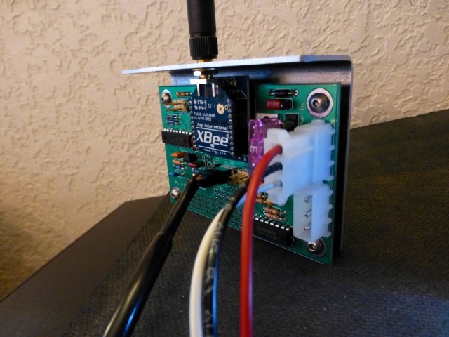
To transmit this data back to the shore, I decided to use XBee modules made by Digi that communicate at 2.4 GHZ. This is the same frequency as the Futaba receiver, but from what I read, the Futaba can shift frequencies to find an open one nearby, so hopefully the two can coexist. These modules should be able to communicate up to about 300' which should be plenty. Going across water is an ideal condition. As a back-up, in case the range isn't enough, they sell the Xbee-Pro modules, which are pin-compatible, and have a range of up to a mile. The down side is that they draw a lot of current (250-300mA) which would use up the batteries pretty quickly. These modules can transmit and receive RS-232 data, but don't do any buffering. Essentially, you put data into the transmitter, and it comes out of the receiver in exactly the same form. Each unit can do bidirectional communications.
In the boat, the circuit is dealing with the depth sounder that wants 12V, the Hall-effect sensors that want 5V, and the XBee that wants 3.3V. I decided to run the PIC at 5V, and found an adaptor board for the XBee that translates signals from 5V to 3.3V. It wouldn't be hard to do that with a couple more components on the board, but this adaptor makes it easier since it's already debugged. The XBee modules are reasonably priced at about $20 each, even for the higher-powered Pro series. Since I would be doing RS-232 communications, I used an external 12 MHz resonator on the PIC, accurate frequency is necessary for asynchronous communications like this.
I write my PIC code in C, using the CSS compiler. This was a pretty straight-forward program. It just stays in a loop getting characters from the depth transducer. When it finds a command (like depth or temperature) it reads that data, converts as necessary (e.g. C to F for the temperature), then sends the data to shore. Once each loop it reads the battery voltages, and when interrupts for the fishing reel occur, it figures out what direction it is going and increments or decrements the counts as necessary, then computes feet of line out from that. I reset it to show zero feet out when you power up the boat electronics.
I laid out a circuit board for this. On it, I left a little bread-board area for adding things later should the need arise. I also put a ULN2003 there so I can drive relays for other things, such as items critically important like a a horn to harass near-by boats. I bent a piece of aluminum to mount the PCB. The XBee modules are available with an SMA connector, so I got one of those for the boat, with a stubby antenna. With this setup, I can have the circuit board inside the front of the hull. Transmitting would be easier with a wood hull, then you could simply have the antenna inside. I'm going to have to deal with this on the Futaba, too. Haven't decided how - right now the receiver has just a limp wire antenna. We'll get to that I suppose, but for now, here's the transmitter PCB in the boat for sending data to shore...
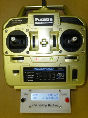
Now that we're able to transmit data from the boat, the next step is to receive it at the shore, and display it. This calls for another XBee, another microprocessor, and a display. I decided to mount it to the bottom of the Futaba transmitter. This is a pretty easy circuit, the 2-line by 20 character LCD display uses I2C serial communications. The hardest part was laying out the circuit board. To keep it small, I mounted the electronics on one side, and the display on the other. To complicate things, the display was off-center from its connections and all in metric. I figured that there was a small chance that my first-offering PCB would be correct mechanically - but by some miracle, it worked. I used an XBee with a little wire antenna, it sticks out the back of the enclosure.
Here's what the unit looks like from the front...
Here's a profile...
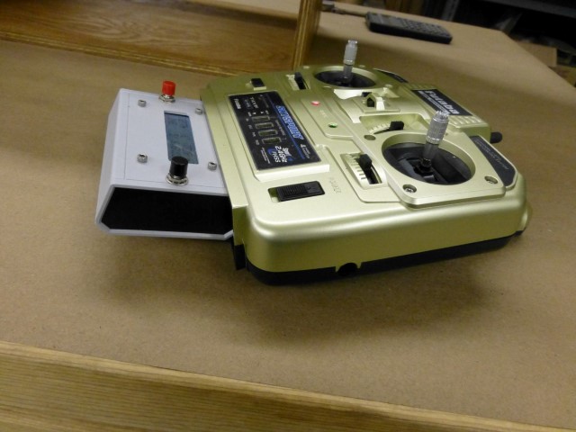
It's just a standard plastic hobby-box that I bolted to the Futaba. I ran wires from the Futaba batteries so that it is all powered on and off by the same switch. Those two buttons are for future use. As you can see, though, I have some ideas.
If you look at the display up close, here's what it looks like...
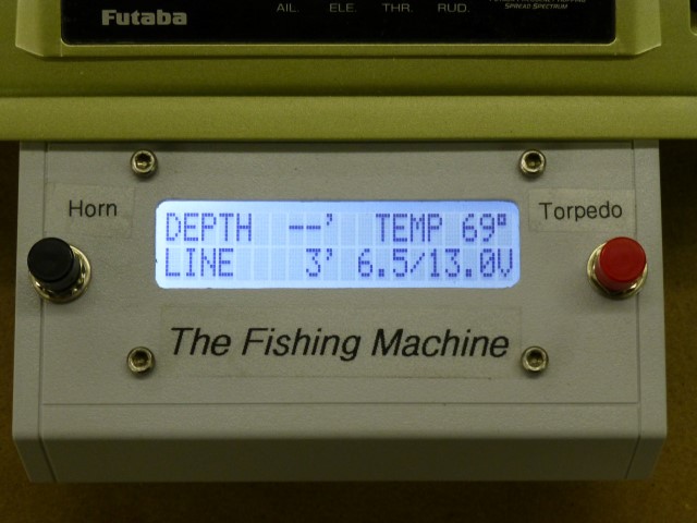
On the top line, it gives you the water depth (from the depth-sounder) and the water temperature (again from the depth-transducer). On the bottom line, it gives you a reading of how much line has spooled out, the voltage of the 6-volt battery, and then the voltage of the 12-volt battery (two 6-volt batteries in series). Pacing the display is the data from the transducer. So I made the / between the voltages flash between a / and a % each time data is received, so that you know it is being updated.
There are some screws holding the inner bulkhead to the hull, several feet of welds, and the out drives - all of which are capable of getting water in the fishing machine, not to mention a wave that could splash into the boat. I thought it would be a good idea to have a bilge pump.
I had ordered up a little 6-volt pump on eBay from China ($14 including shipping), and figured that I would turn that on and off with a float connected to a micro-switch. I tried a cork as a weight, and found that it didn't come close to having the buoyancy to trigger the switch. So I dug out the spec sheet for the switch, and found that it takes 80 grams to actuate it, and this turns out to be a couple cubic inches of water displacement - the float would have to be huge. Things are starting to be a little more complicated than I thought.
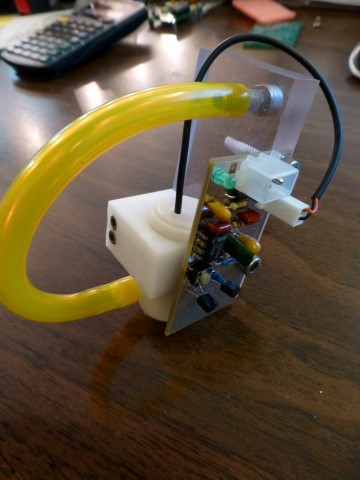
So I decided to see if I could make an electronic circuit. You're probably thinking - "Is this donut going to use yet another microprocessor?" Actually not! I came up with a little circuit with a 555 timer IC and a couple transistors to sense the water resistance and actuate the pump. I made it so that whenever it is triggered, it would run the pump for a couple of seconds at a minimum. The thought is that this would keep it from cycling on and off a lot. I made the PCB have some fingers close to a ground plane that the circuit would use as the water sensor.
Water by itself has virtually no conductance. It's the minerals and impurities in the water that give it resistance. I sampled our well-water (has some iron in it) and some "purified" water, and indeed there was quite a difference. But the circuit could be made to sense both just fine. Here is what the sensor looks like...
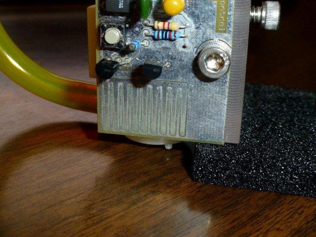
The little button you see above the left transistor is a test button. Here's what the whole assembly looks like...
The plan is to mount it against the transom with two cap screws. I drilled a hole through the top one, and water can squirt out through it.
So, how does it work? Well, I ran into two problems. The first is that the centrifugal pump won't reliably prime unless it's way into the water. I figured if the impeller part was completely submerged, that would be enough. I e-mailed the seller of the pump and found out that it is designed to fully submerged. That wouldn't be practical since it couldn't work unless there was over an inch of water in the boat. The other problem I found was that when the sensor was submerged for a little while, there was too much water left between the sensors, and it didn't turn off reliably.
Time for the second offering of a bilge pump design. While the first pump could be directly driven with the 555 output pin, any other pump I found drew more current than was available. Fortunately, when I laid out the PCB, I made provisions for a little relay, so higher-current devices could be switched. I went to the local Pick-N-Pull and got a couple of windshield washer pumps. Since we now have 12V in the boat, these could be adapted. Most were centrifugal pumps, but I did find a Volvo pump (made by Bosch) that was a diaphragm pump - unfortunately, it was kind of big and clunky. So off to eBay I went, and found a 12V diaphragm pump from China. Again, it was cheap, even with shipping, but needed a few weeks to arrive slow-boat.
So my second design looks like this, and it works well...
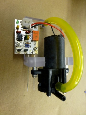
The bottom tube is the water pick-up. Those two "wires" hanging down are the water level sensor. I cut off the bottom of the original PCB and soldered these in place. They almost look like paper clips, don't they? No coincidence.
Here's what it looks like from outside the boat, when mounted - again, the top screw is the discharge port via a hole I drilled through it..
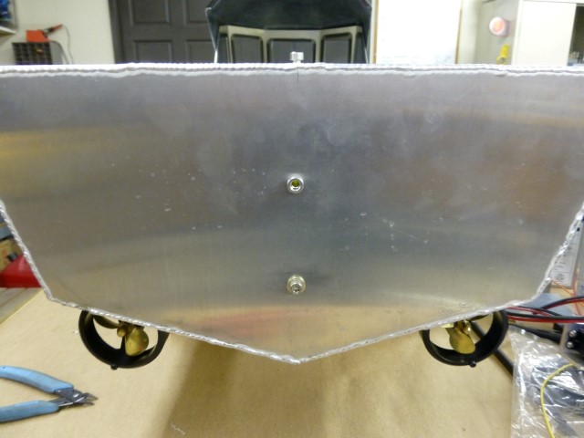
Here's what it looks like from inside the boat...
I know it looks like the drive motors are offset in the this photo, but they aren't really. Maybe the far one wasn't bolted in at the moment.
It seems like an important feature of a fishing machine is that it has a loud horn. How else are you going to be able to harass ducks and real boats that are nearby? I found a flush-mounted horn that is 108 dB, and draws less than an amp of current at 12V. It's Coast-Guard approved for boats up to 20 meters. Should be OK for my boat that's just over one meter long. It's meant to be mounted vertically, but the only good place I could find was the fore-deck, and it will require horizontal mounting. There are drain holes inside it though. Another reason for a bilge pump.
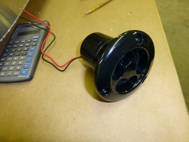
My shop is about thirty feet from the house, and as I experimented with it (doors closed on both buildings), my wife tells me that its loud inside the house. Should be good enough! Too much is just right. Actually, when in the outdoors it isn't all that loud. Dang.
I installed another little relay on the prototype area I put on the XBee board in the boat that drives the horn. When I push the button on the transmitter side, it sends an "H" character to the boat from the shore, which blows the horn.
A disadvantage of a metal boat is that RF signals can't go through it. The Futaba receiver has a little coax wire that serves as it's antenna. I decided that I better do something to get the signal to the outside of the boat. I found a site that showed how to snap apart the case on the receiver. Turns out that the original wire antenna is connected inside with a connector style called U.FL, and I found a short U.FL to SMA cable at Digi-Key, that way I can have two matching antennas on the deck, one for the Futaba, and one for my XBee communications.
Here's the receiver with the new cable installed, below it is the original wire antenna.
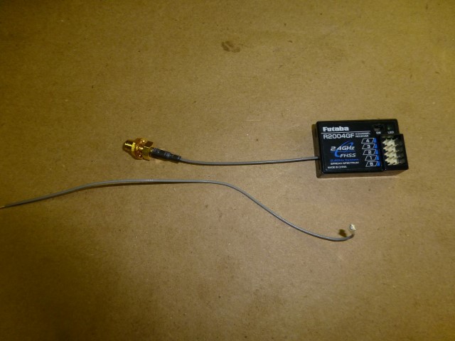
I can assure you that there are lots of tiny components inside that receiver - glad I'm not trying to solder it together.
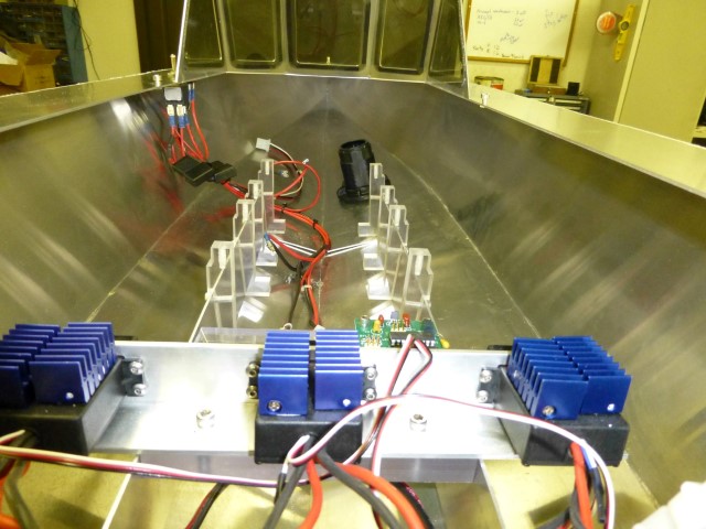
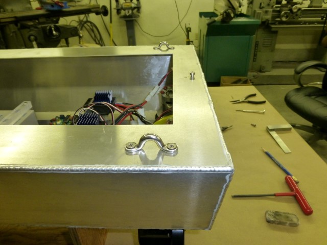
I'm finally to the point where I have all the major building blocks done, so it's time to start drilling more holes in the boat and installing them. Here are some random shots, in no particular order.
This is what the depth/temperature transducer looks like from the outside of the hull.
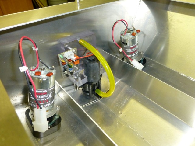
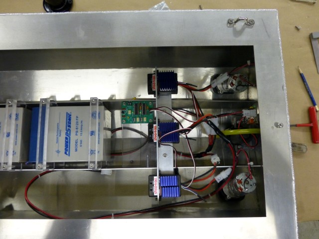
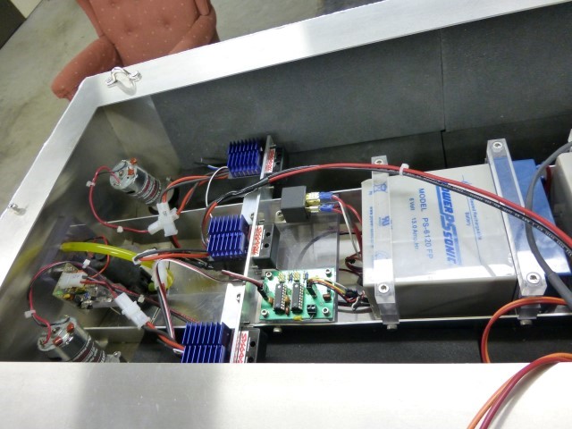
Here's the ESCs mounted up (two for drive motors, one for reel), and the PCB that converts joy-stick movements to motor speeds for turning. There's room on the other side for a future PCB or power relay if necessary.
I made the battery mounts from some scrap Lexan. You can see the inside of the transducer up there, and also the switch wiring on the left. I put a couple of in-line fuses there (one for 6V, another for 12V). Surprisingly, I need a 20A fuse for the 6V line to the three motors.
I mounted the Futaba receiver with some self-adhesive Velcro. It needs to be mounted close to the antenna since the lead is short. This does give it some vibration protection and keeps it out of the weather. To the left of it you can see the horn. I left a couple extra wires in the bundle to the receiver - we still have a channel left. Will be fun to see how to use it someday.
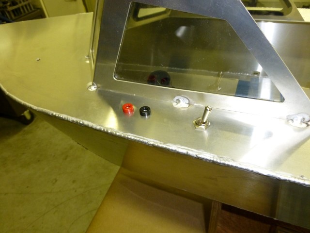
Just outside the "cabin" I installed an on/off switch that powers everything on the boat. I put two banana jacks there so that I can connect a charger. Since they are on 3/4" spacing, a standard dual plug fits them.
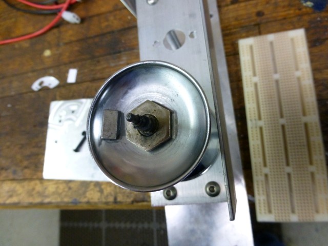
About this time, I decided that I better see how much this boat weighs now. It's not light!
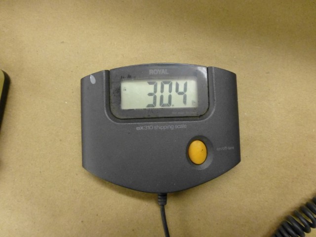
That started me thinking that it's going to be hard to lift this boat into and out of the water. So I installed some hooks, two in the rear, one on the bow. I'll make some sort of bridle to lift the boat.
After some deliberation, I figured out a scheme for cutting the fishing line. This might be necessary in the case of being snagged, or if too big of a fish hits the hook (wishful thinking).
In a perfect world, I could buy a thick piece of nichrome wire, form a ferrule on the rod, then apply power to it so that it would get hot and melt the line. Unfortunately, if you get wire this large, it takes way more current to get up to temperature than one could use on a battery-powered boat. And the smaller gauges of nichrome aren't all that strong. I rounded up a piece of 26 AWG nichrome wire, and according on-line charts, I needed about ten or eleven inches of it to keep the current down to a level for not overloading the batteries, yet hot enough to melt monofilament fishing line, which takes a minimum of about 150 degrees C.
I thought that maybe I could use some heat-shrink tubing to insulate the wire so that I could make repetitive loops, and hence make it stronger, however my experiment with that resulted in some smoking and bubbled heat-shrink tubing. I found that Lexan (polycarbonate) has a fairly high melting point, so I decided to make a nichrome holder out of that. I machined up a little block of Lexan with some holes that would route the wire against the bottom so it was rubbing on the fishing line, but with the Lexan providing the mechanical support. Then I laced the nichrome wire on it (to get the desired length), and connected it to 12V battery power through an automotive power relay. It's controlled by the microprocessor that is communicating to shore. When a button is pressed on shore, it sends an ASCII "C" to the boat, which triggers the relay for a few seconds, then shuts off power to it. I used a ULN2003 IC to power the relay for this, and also the horn. To trigger the cutter, I made the shore transmitter require a keypress sequence that would not easily happen by accident - hate to have a big fish on, then accidently cut the line.
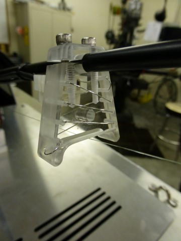
Here's what it looks like installed on the fishing pole. It's located so that the line brushes past it between two ferrules. The pole is arced in this picture since I have a pair of pliers hanging from the end. The goal is to press the button, and watch the pliers hit the floor.
Here's what it looks like up close.
And you can see the power relay here, just behind the battery. Getting pretty busy in there!
The cutter seems to work fine (the pliers did hit the floor!), but with any luck, I'll never need it.
At this point, the boat is mostly done, but I have yet to do any serious sea-trials.
There are still many things I'd like to do. Here are some -
1. Install some foam inside. I've ordered up a sheet of closed-cell foam that I plan to line some of the hull with. I think this will serve two purposes - quiet the boat down, and provide some flotation in the event of the unthinkable. It's still not enough flotation though. I figure that I would need almost a cubic foot of the stuff to overcome the weight of the fishing machine. Water is about 62 lbs/cubic foot (salt water is heavier at about 64 lbs/cubic foot), and this boat weighs over half that. As an alternate, I'd like to find a way to have an inflatable buoy or some such that would inflate if needed to hold the boat up, or at least mark where the boat is under water. I've got quite a bit of energy into this rig, and I'd hate to lose it to the bottom of the lake. Suggestions?
2. It would be nice to have a sensor on the line that could detect if you have a fish on. With that, I could even blow the horn to alert me while I'm on shore and not paying attention.
3. It needs some paint or decoration on the outside.
I'm sure this will be a work-in-progress for quite a while.
That said, I'd just be plenty happy if it works as is. I'd love to haul in a big fish! I'll update the site when that time comes.
I finally had an opportunity for it's trial mission on a friend's pond. While I didn't catch a fish, it was mostly successful. Here are comments from the run:
- It steered really well. In the clip, if you watch the prop-wash, you can see it going backwards on the inside propeller.
- I found that the depth sounder reads about 1/3 of what it should - I'll need to multiply by 3.28 since the transducer is evidently outputting data in meters rather than feet, like I thought.
- It leans to one side. Evidently that's from having the reel-motor and drive mechanism off-center. I guess I'll have to add a little off-setting ballast to make up for that.
- The only other thing is that it sets off rather quickly, even if you don't have that in mind. I'm not sure whether that's just the nature of the motors/ESCs, or whether I can fix that by recomputing the throttle to be logarithmic in progression. I'll have to experiment a little with that.
But, it's getting very close to being ready to head out on "big waters."
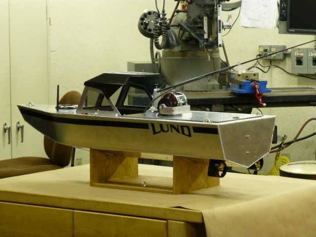
Didn't take much weight to level it out, then I reprogrammed the depth micro to correct the depth-sounding error, and put on some graphics...
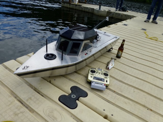
My regular trout-fishing boat is a Lund 1600 (which means 16' long), I guess this boat is equivalent to a Lund 400.
I took it out for it's first "real" fishing mission on our annual trip to Conconully in eastern Washington. Caught three Rainbow trout with it in about 30 minutes.
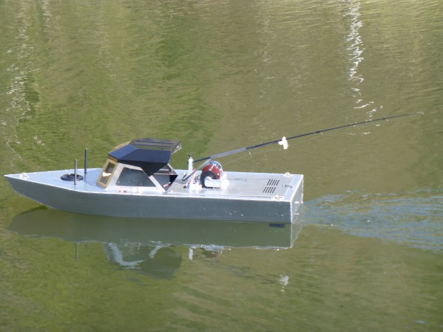
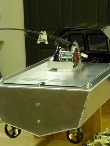
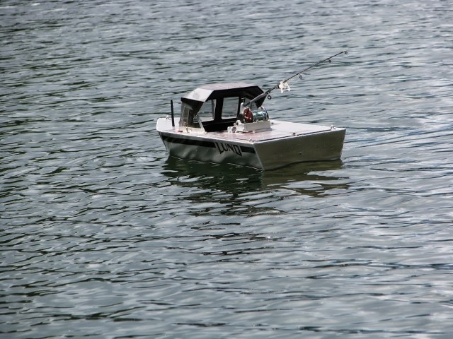
Here it is out on the water...
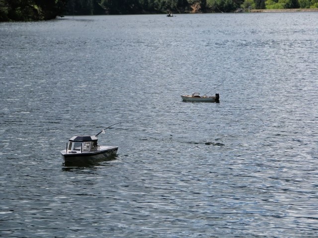
Here is another shot of it. Also in the picture is the "work of art" handmade boat that my brother built from scratch, its a 32" boat patterned from a Monk design. I have a fish on my boat at the time, note the arc of the rod and the current behind the boat. They almost look like real boats out there...
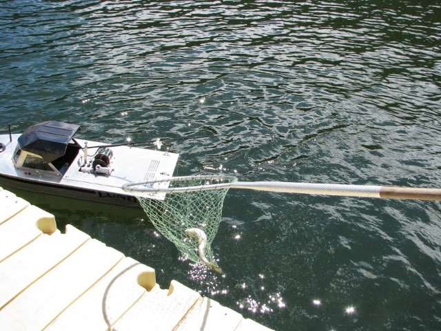
Here we are netting one at the dock. The fish it caught were 10"-12" long trout.
Finally, here's a shot of the fishing machine with one of it's catch...
My son-in-law, Zac, captured part of a catch with his camera, it is here...
Landing a trout with the fishing machine...
Hope you've found something in these ramblings to be of some interest.