Automated Laser Leveling Project
Brian Laine 2/2022
The problem:
Last fall, we (meaning my wife, Chris, for the most part) had to redo a horse arena, which involves bringing in more sand and other materials then grading it all level. There’s a rock base below the material, and only about 2 ½” of soft material, so the grading needs to be precise to prevent digging into the base. About +/- ½” is target grading tolerance.
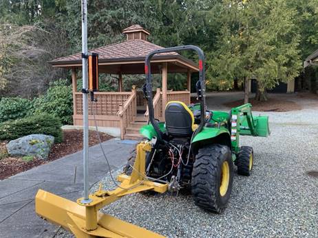
We used a back-blade on our tractor which requires use of the 3-point control lever to set the height. In the grading area we used a rotary laser, and I mounted a pole on the blade to accommodate a laser receiver. The receiver looks at the rotary laser signal, and displays arrows telling you if you are on-grade, or above or below it.
This works OK except it is very slow and cumbersome. You need to stay twisted around on the tractor to see the arrows, and the hydraulic control wants to move in larger increments than you want, making it more difficult.
The proposed solution:
I noticed that the laser receiver was made to accommodate an optional remote display, so I thought maybe I could tap into the system, get that information, and make the blade move up and down automatically. I contacted the manufacturer and was told this wasn’t possible, and they weren’t going to share any information about the signals to and from the receiver. A challenge! After spending some time with my oscilloscope, I found that I could decode the pulse train on one of the pins to get the information I needed. Good start to the project!
Next question was how to control the height. Even if a tractor has rear hydraulics (and most smaller tractors don’t), it’s not easy to remotely control the flow from the rear hydraulic outputs, over-riding the factory valves. So instead, I decided to use an electric linear actuator as the top link of the 3-point setup. By controlling the length of the top link, it makes the blade go up and down. I found an actuator that works on 12v and can move up to 2,000 lbs.
Now, I had to figure out how to make this stuff all play together. I planned to make some electronics that will allow the user to run the linear actuator all by itself (no laser or hand-held) which is handy when putting implements of any sort on, so it needed a switch on the actuator for that purpose, even if used stand-alone and left on the tractor all the time.
Then, I planned to make a hand-held control device that would allow you to run it up and down, would give you the same arrow information as the laser receiver (but this time when you are looking forward), and ultimately control up and down automatically.
The plan was to add an electronic circuit to the linear actuator as the core of the system, then have cabling from that going off to the laser receiver, the hand-held, the actuator motor and sensor, and power.
Implementing the plan:
Laser Equipment
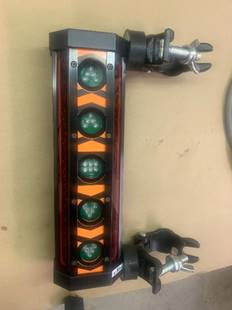
I’m using this laser receiver. It comes with magnetic or pole mounting provisions. It can sense the laser signal from all four corners.
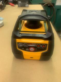
This is the rotary laser I’m using – any red-laser signal will work. It mounts on a tripod, self-levels, and the receiver is adjusted up or down on the pole to set the zero position. Slopes can be set on the rotary laser if you want to grade with drainage.
Linear Actuator
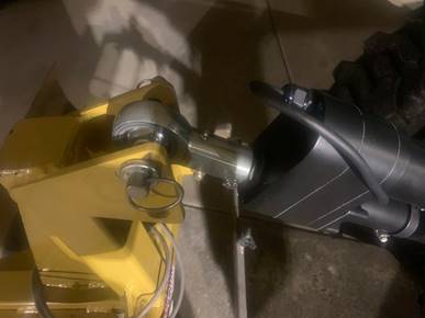
The linear actuator has an 8” stroke and was the right length after I machined some Heim joints to fit on each end. Oddly, the actuator was slightly different on each end. I used the correct size for a Cat-II hitch, but it can be used on a Cat-I hitch with a bushing at each end. So, it should work on about any size tractor, long as it isn’t asked to move more than a ton of implement weight.
Connectors and cabling
For connectors, I decided to match the circular connector that the laser receiver had. Of course, the manufacturer wouldn’t tell me what they were, but I figured it out. For power, I first was going to use a flat SAE connector like used on trailer lighting, but in a 2-pin rather than 4-pin format. I mounted one of those on my tractor with an off/on switch on the dash – it’s also used for our sprayer attachment. I was a little nervous about the power capacity of this connector, so I ultimately used an XT connector which takes a lot of power and is readily available in hobby shops for RC rigs.
I found some high-quality cabling which, while not cheap, is well suited for this application. I ended up with male and female 4-pin and 7-pin circular connectors. Figuring out the cabling was made a little more complicated because I wanted the hand-held to also be able to plug straight in the laser receiver instead of the actuator to allow it to serve as a hand-held repeater, even if the installation didn’t have the actuator.
Power Circuit on Actuator
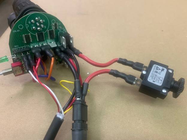
I designed a circuit board for the actuator that uses solid-state devices (MosFETs) to control the cylinder power and serve as a core for the other cabling. I wanted to avoid the use of relays which can fail if constantly cycled. The most complicated part of the circuit is some digital logic that prevents the possibility of having the two switches (one on hand-held, one on actuator) telling it to go different directions at the same time, which would cause some serious damage. I decided to 3D print an electronics enclosure with ABS. This made it practical to mount the electronics and connectors in an inobtrusive way. I need to print it in halves (parting plane shown) in order to assemble it.
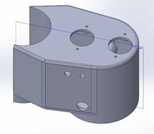
To fit this, the circuit board had to be a pretty odd size - horse-shoe shaped. This picture also shows the 20A breaker I put into the system, just in case. You can see the XT connector at the bottom.
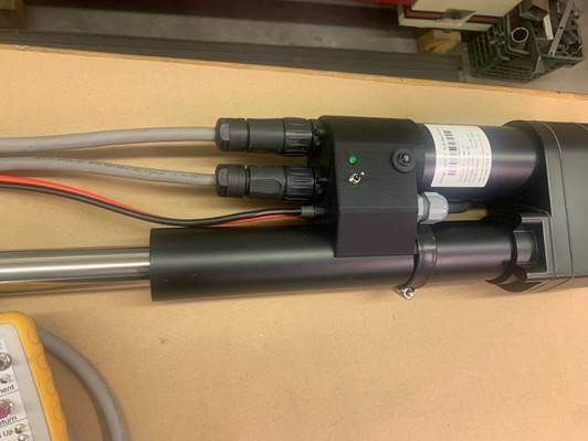
This shows the finished unit mounted on the cylinder. Guess I’ll need to find a black gland to replace the gray one I used in the rear of the enclosure.
Hand-Held Unit
For the operator control, I wanted to be able easily see what the laser was doing, be able to control the actuator, and do the automated control. That means a microprocessor since it also needs to be able to read and decode the critical timing of the signal from the laser receiver.
I found an enclosure with a protective rubber boot that was about the right size and easy to hold in one hand. It has a removable panel on one end where the cable comes in. It was easy to just 3D-print this part rather than drilling the one that comes with the enclosure. This allowed me to also provide a thicker boss area near the connection.
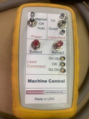
It has a power switch: off, manual or automated. Another spring-loaded toggle switch that allows you to control up and down, along with two buttons for the same purpose – but easier for some to use than the toggle switch. I made it so the switches are active while in automatic mode so that the operator can override the computer.
There are LEDs that:
- Display power on,
- Display whether the actuator is being commanded up or down (manually or automatically), and
- Replicate the laser receiver arrows. I used green for middle (on target) and red for the laser indication up or down arrows. If the signal is far from zero, the direction LED blinks rather than stay steady to show that a major correction is necessary.
The actuator has an optional resistive potentiometer that gives the distance extended. I built the circuit board with an ohmmeter to read this signal. I also made provisions for saving a position, saving high and low travel limits, and returning to a saved position. In the end, though, I decided that these features aren’t necessary, and added to operator confusion, so I simplified by leaving them out. Still there on the circuit board and in the microprocessor code, but not used at the moment.
Results
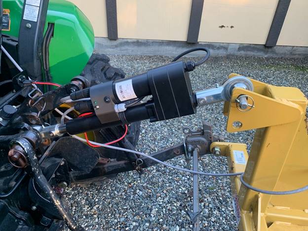
Here’s the setup installed on the tractor…
When I first embarked on this project, I thought it would take a few days, certainly less than a week. Wrong! I’ve been at it for months between designs, design changes, waiting for parts, … Wasn’t as simple as I first thought, but I’ve learned a lot. And enjoyed the project, at least most of the time. Always fun to go a little different direction in projects.
My thanks to an engineer friend, Mark Olson, who helped me by reviewing my designs and helping me solve some of the problems encountered.