
Gator EV Project
Brian Laine - Jan / 2023
Im not sure what the target audience is for this story. Its about converting an old gas UTV to be electric-powered. It might be of interest if you want to get an overview of EV (electric vehicle) building blocks and how they fit together. It took me a while to get the picture, and Im still learning. More specifically, if you are interested in a similar project, it might give you some idea of how to deal with some of the mechanical or electrical challenges, and also how many details need attention. Ive included lots of pictures and a fair amount of text, so it is likely pretty boring to most folks. On top of that, there are some pictures that are similar, but are first shown during the fabrication stage, and then again all painted up in the final assembly stages. Redundant, but each picture, although similar can provide more details from being a little different view and background.
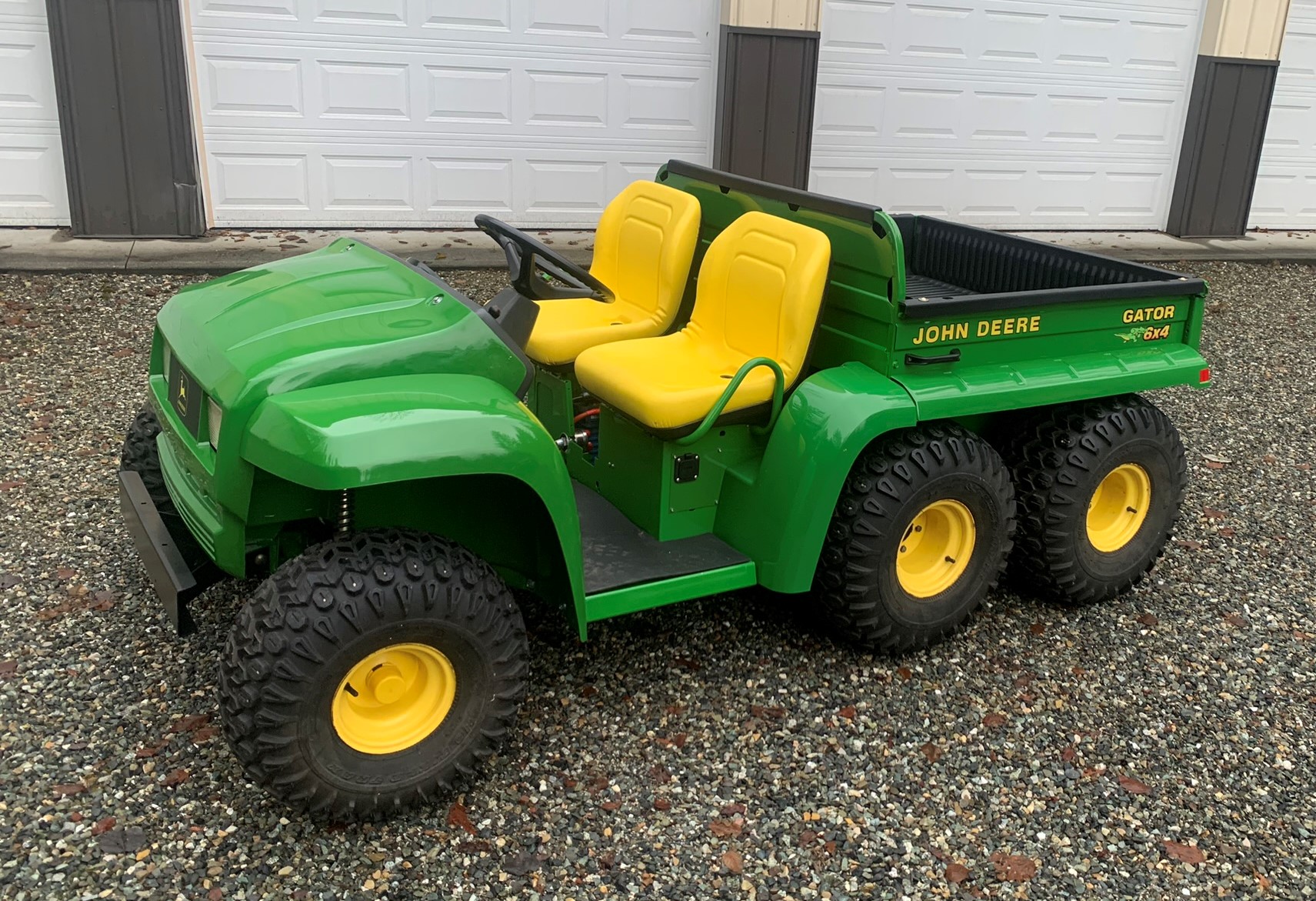
About two or three years ago, we had a field fire with our Gator 6x4 in the middle of it. The presumption is that the Gator started the fire. We were using it while picking weeds and such from our hay windrows. It had been used for manure-hauling every day, but fortunately, we had a similar backup Gator, so we turned the daily manure duty over to that machine. In any case, the fried Gator had given us our moneys worth its about twenty-five years old, and was looking rough from wear and tear even before the fire, so I could have junked it without guilt. It didn’t have an hour meter, but it has a lot of hours under it’s belt.
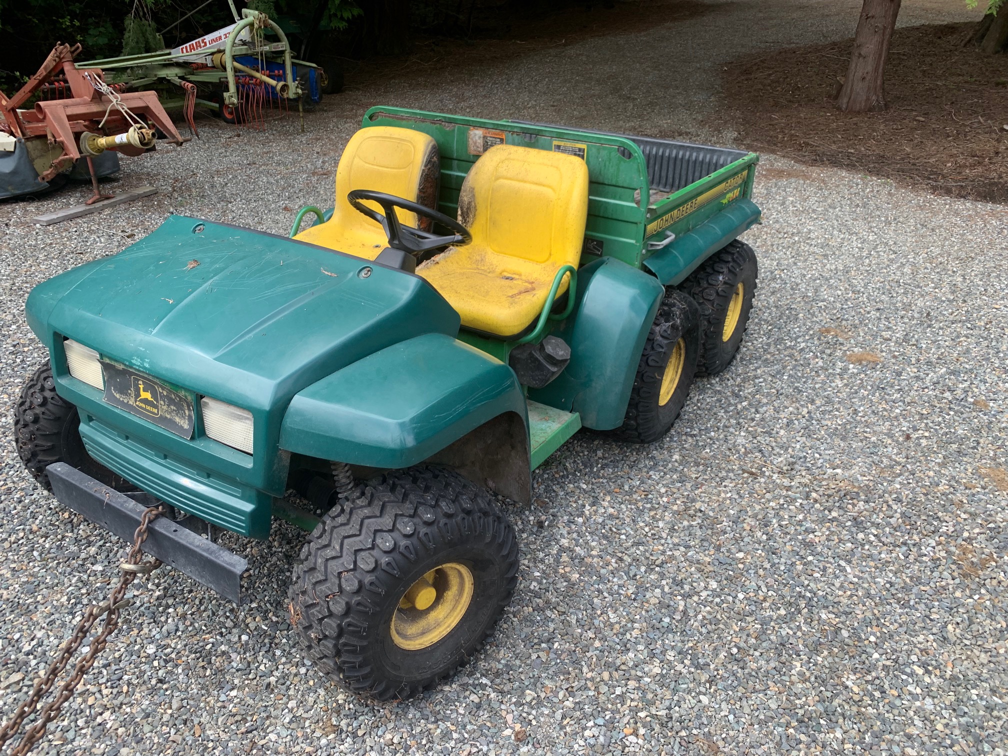
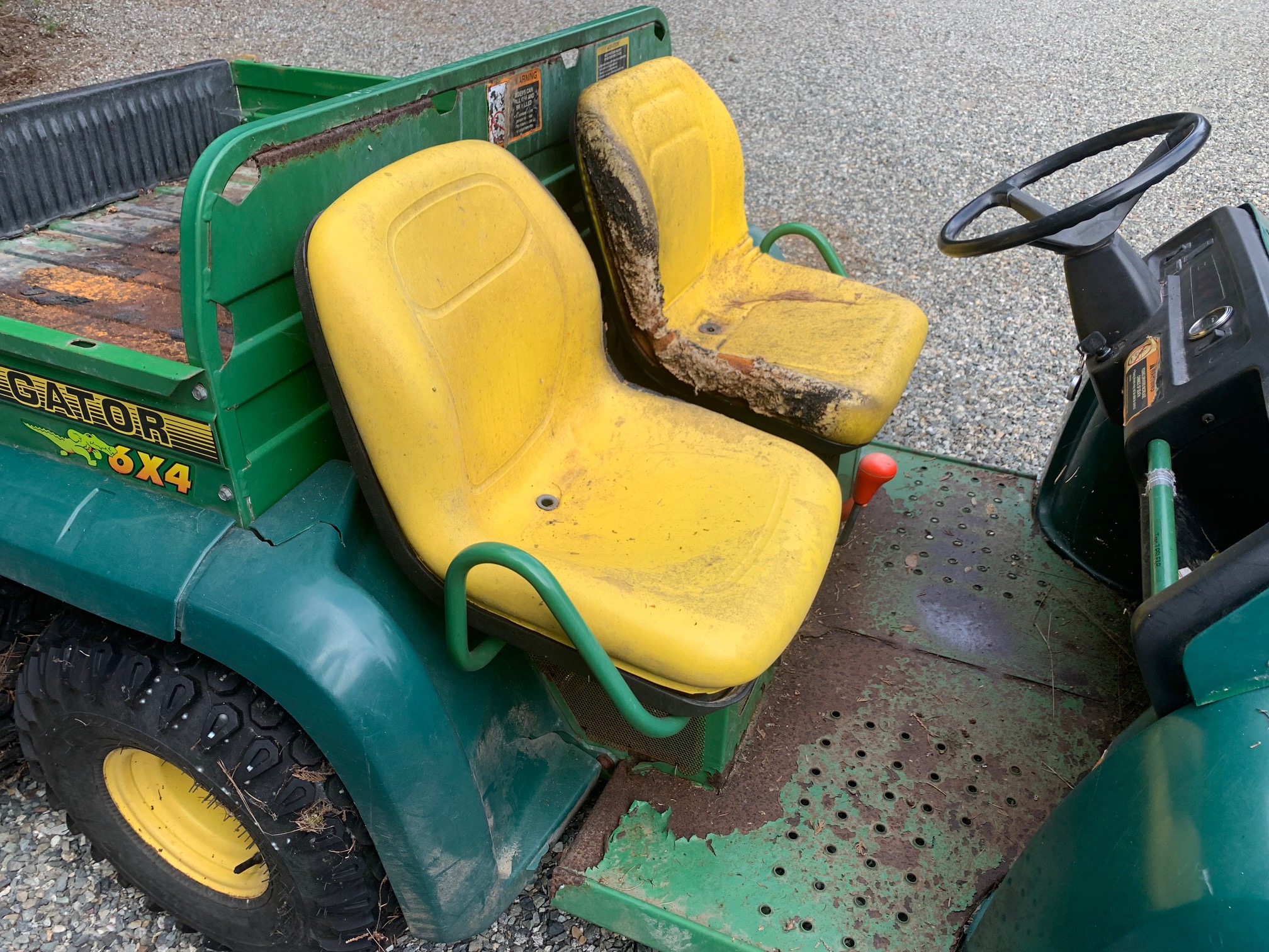
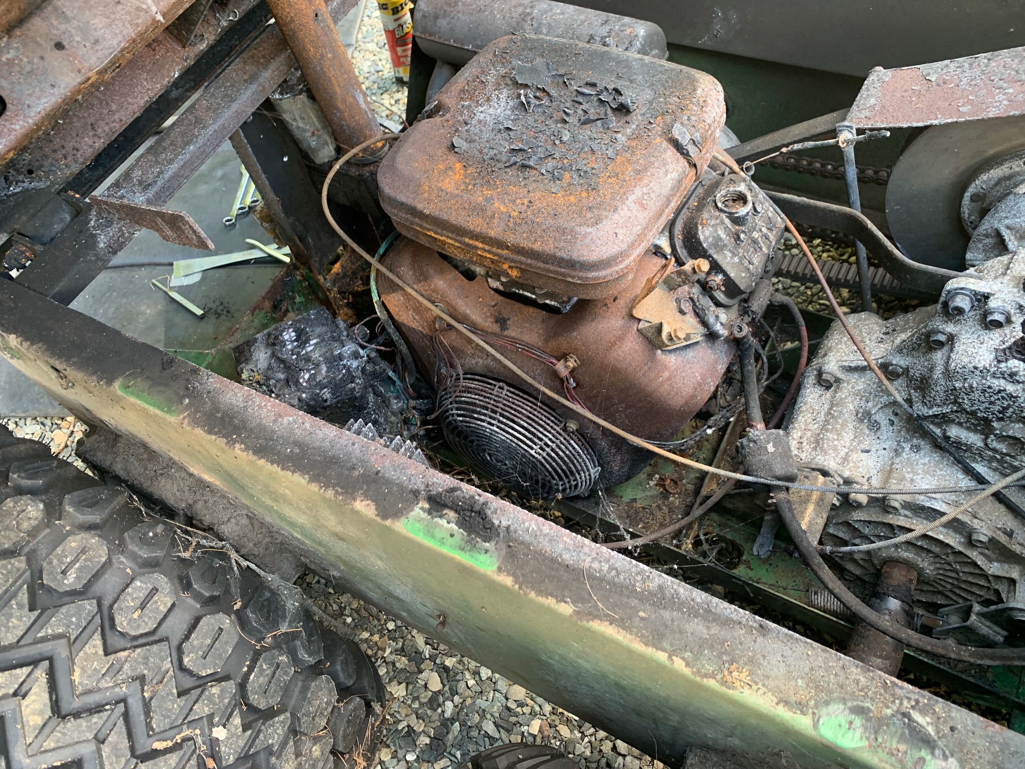
Here are some shots of what it looked like after the fire
Here's the battery, probably unlikely to be a core-return...
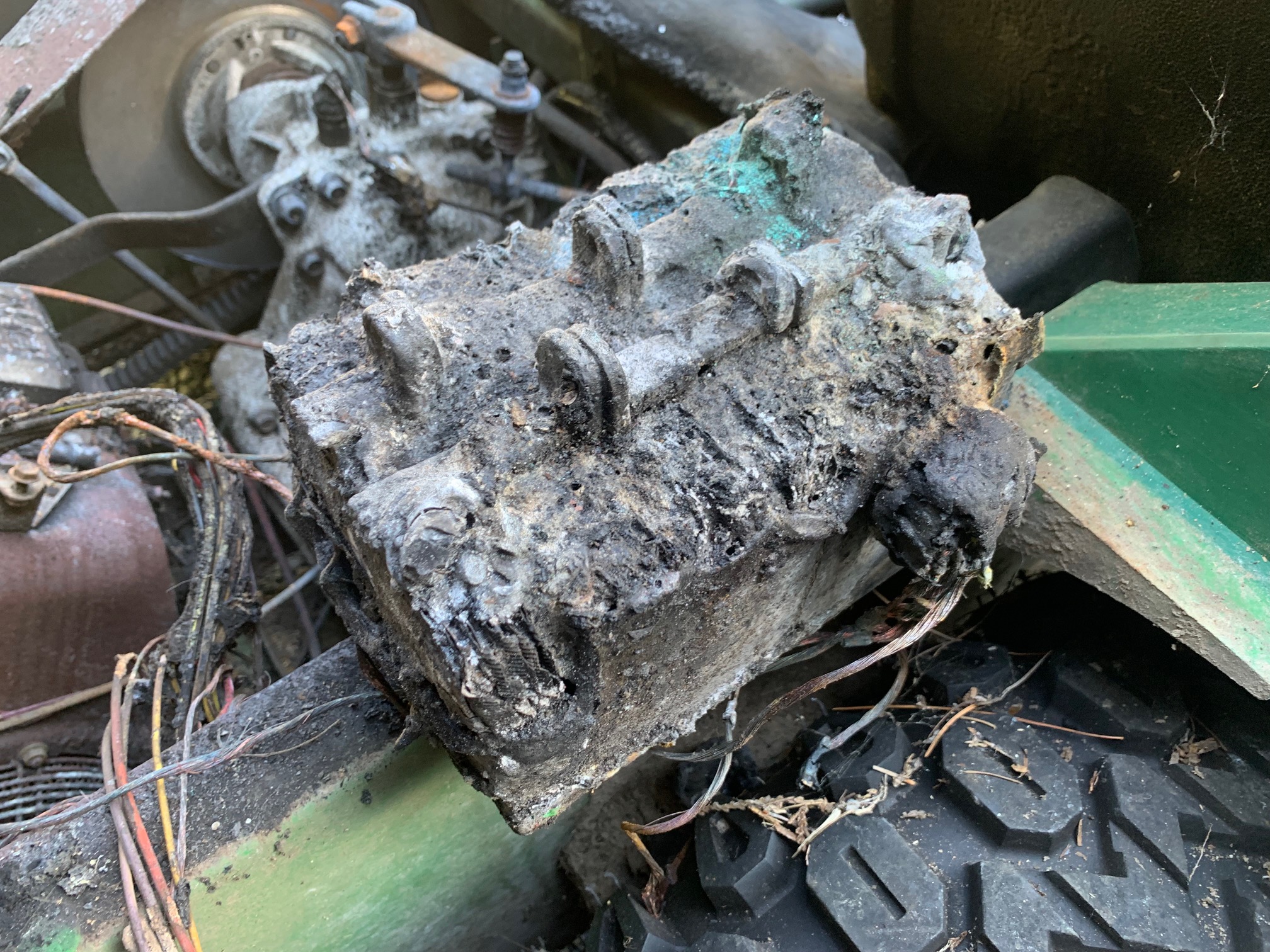
Pretty rough shape. A lot of the plastic parts and wiring were melted, seats melted on one edge, side burned out of one of the tires. It has a plastic fuel tank, and while much of it was melted during the fire, it still had a fair amount of fuel in it could have been a big boom!
Ive been thinking about that old Gator, and what to do with it.
I decided to haul it out, then see if I could convert it to be a purely electric vehicle (EV), and rejuvenate it at the same time. A few years ago I bought a crate of LiFePO4 batteries inexpensively on Craigslist from someones failed EV project, so I have at least one of the ingredients.
Not that I know anything about electric vehicle design although Ive never let lack of knowledge slow me down in the past.
I decided that it needed about a 10KW power plant. The old engine was 16 HP, and theatrically a 10KW motor would be 13-14 HP (746W/HP), but with an electrics flat torque curve, this should match or outperform the original.
The next question was whether to use the original drive-train. This consists of a variable-ratio Gilmer belt-drive connected to a gearbox / differential. The gearbox provides forward and reverse shifting, brakes, and connects on each end to the front drive-wheels. From those wheels, there are roller-chains that connect to the rear wheels.
Looking at the size of the motors in this range, I can see that there are a couple of problems if I use the original gearbox. One is that the motor is long enough that if I lined up with the gearbox input, it would hit the wall of the Gator just too long. Next issue is the fore-aft size of the combined gearbox/motor it leaves very little room for the batteries. Also, I didnt need the variable speed drive, nor the forward/reverse part since the electric motor can simply reverse electrically, and has enough torque to not need gear ratio changes.
I shopped some sites, and found a supplier than could sell many of the parts to make a package consisting of the motor, a gearbox, a motor-controller, a gas pedal (throttle), a DC:DC converter and even a little instrument cluster (dashboard). It turns out the package comes from China but that is the way of many of the EV parts I had to deal with. I guess these parts are made for small EVs, but I specified the lowest gear ratio I could order, should be about right for a 20-25 MPH top speed. Hard to figure the speed - the motor is rated 2,750 RPM, but says maximum RPM is 6,500 - and I don't know which of these numbers to use. At 2,750 RPM, the top speed calculates to be 20.4 MPH. These parts are from Foshan Uni Technology Co, Ltd, via Alibaba.com
After getting the rough dimensions of the parts, I made some measurements, and it looks like I could get 22 batteries into the system. Sixteen behind the motor, and three under each seat, taking the place of the gas tank and radiator, which are no longer needed. Since these are nominally 3.2v batteries, that gives 72 volts, which is one of the standard EV voltages, although it is high enough that you really dont want to be touching it. Anything more than about 50 vdc in dry conditions, or 25 vdc in wet conditions could shock a person. But more voltage equates to less current the reason power lines run super high voltages, then convert that down to 115/230 for use in our houses.
Im used to dealing with higher-powered gas engines in cars, so they dont seem too intimidating. But, having electric power is a bit scary since I dont have much experience with it. And we have all heard the horror stories of trying to put out battery fires. To give you an idea, these batteries can put out up to 800 amps when shorted, and in normal operating conditions, provide up to about 400 amps. Most homes have 200-amp services that run the whole house. I found that I need to use #2-AWG cable big stuff.
This should be pretty easy I thought order up the motor, gearbox and controller package then fabricate some mounting brackets for it and batteries, and do a little wiring maybe take a couple weeks once the parts get here? HaHa as I look back at this though. Although I did do a more extensive restoration than I originally planned. I probably worked on it off and on for about six months.
I ran my tentative wiring diagram by one of my very nice TechnoVersions customers who does EV conversions and asked if he had any advice. His advice was to make sure I had a fuse for each bank of batteries (I will have three banks) each in the 400A range. He also corrected an error in my wiring I had assumed the battery pack would be grounded on the negative end, but the voltage should be kept floating. Also suggested orange power wiring to indicate voltage hazard. He also recommended that I balance the batteries. This process consists of connecting all the batteries in parallel discharging them, then charging them. This forces them to have similar charge/discharge characteristics when they are connected in series.
Then, in talking with the motor manufacturer, I was told I should have a BMS which is a battery management system. So, I ordered one up. This helps protect the batteries and adds safety to the design. See below for more detail about what this unit does.
Here are the major parts that I used in the conversion:
22 LiFePO4 batteries, 3.2v nominal, working range 2.5v-3.6v, 100 amp-hour. LiFePO4, often called lithium iron phosphate. These batteries are safer than standard LiOn cells. However, they are older batteries, 200-400 amp-hour versions are now available in the same size. They weigh about seven pounds each. Mine are rated for 2,000 charge/discharge cycles before losing 20% of their capacity. Typical of EV car batteries today, although some are rated to 3,000-10,000 cycles. Note that in a car, if you went 150 miles per charge, 2,000 cycles will get you 300,000 miles before a battery pack gets to 80% capacity.

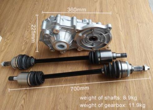
The gearbox includes the differential and has a 10:1 ratio with CV-joint axles each side. I wont be using the outer CV joints on the axles, I'll need to figure out how to couple to the Gator splined shafts on the axles. With the 10:1 ratio, it should go about 20-25 MPH at the motors rated RPM.
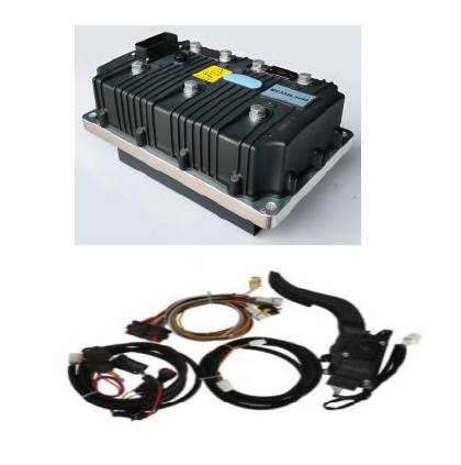
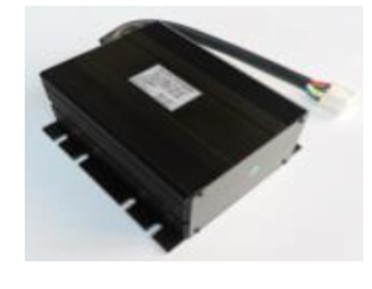
The controller converts 72vdc into the three-phase AC signal that the motor needs to control speed and current. It can also provide energy back to the batteries when the brakes are applied (regenerative braking). The on/off switch and gas pedal inputs go into the controller. This shows the controller, gas pedal, on/off switch, dashboard and wiring harness. It also includes some bags of bare connectors and terminals necessary to make the rest of the wiring.
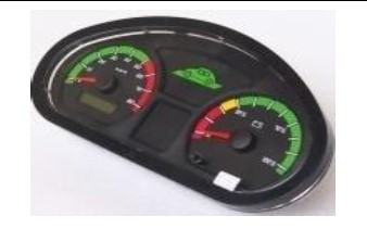
The instrument cluster shows speed (in KM), battery charge level, and indicators for lights and brakes.
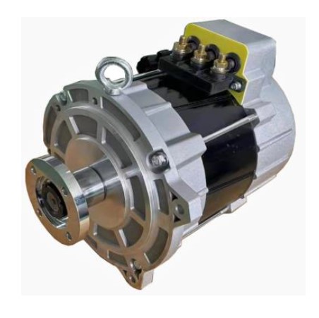
The power is from a 10 KW AC induction motor that can generate power up to 30 KW peak (40 HP!) if the controller commands that. It runs at 2,750 RPM (max 6500). Weighs about 100 lbs. Some of the motors available today are permanent magnet designs - these have some advantages over the AC induction motors, but are also more expensive.
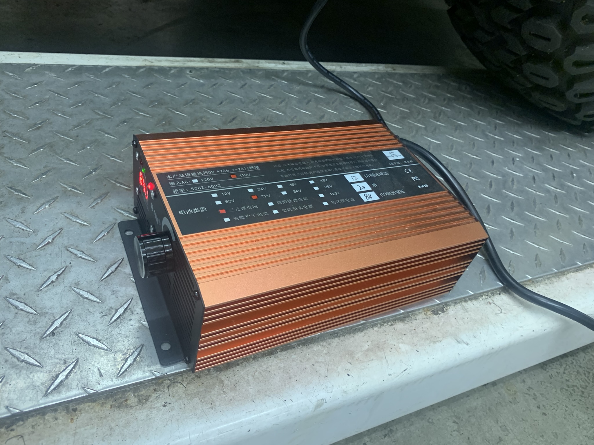
The charger is designed for a 72v EV. It charges at about a 12A rate from a 115v outlet, and terminates charging at 79v, which is about 3.6v/cell. If room allows, I may try to mount it on-board, we'll see how things go. It's about 10-12" long, to give you an idea of the size. 12A may not seem like much if you are used to 10-12 Amp battery chargers, but remember that 12A at 12v is 144 watts, while 12A at 72 volts is 864 watts. Should be enough to recharge overnight, regardless of how much power has been used.
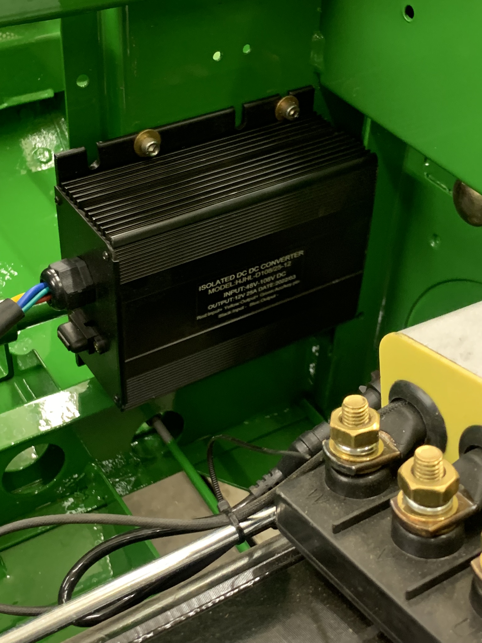
This takes the 72vdc from the batteries and generates 12vdc at 25A. We need 12v to run the bed lifting actuator, lights, and auxiliary output plug on the back of the machine for use with a sprayer.
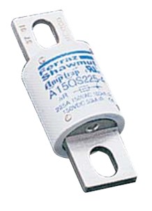
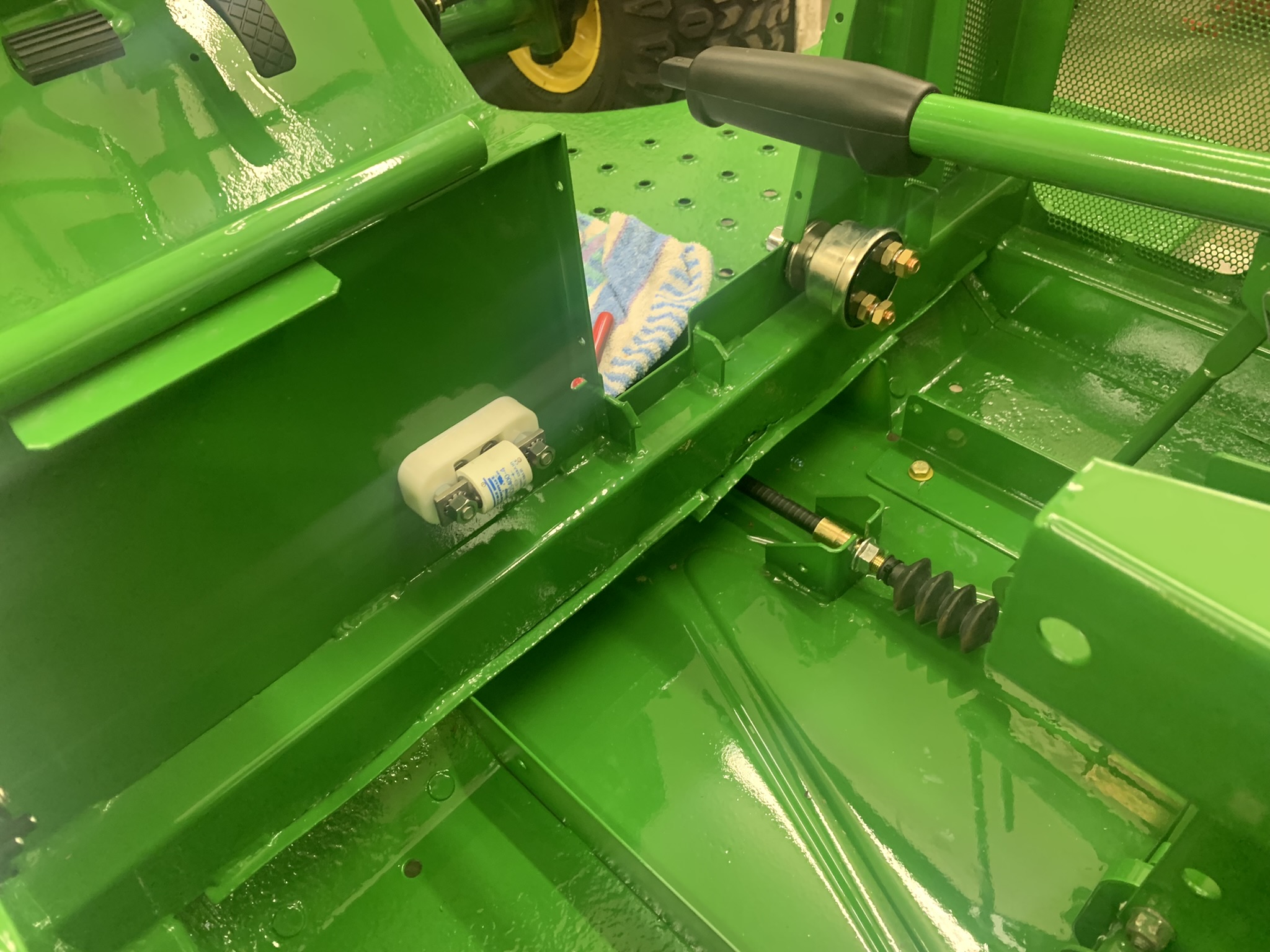
I used 400A solid-state fuses, one per battery bank.
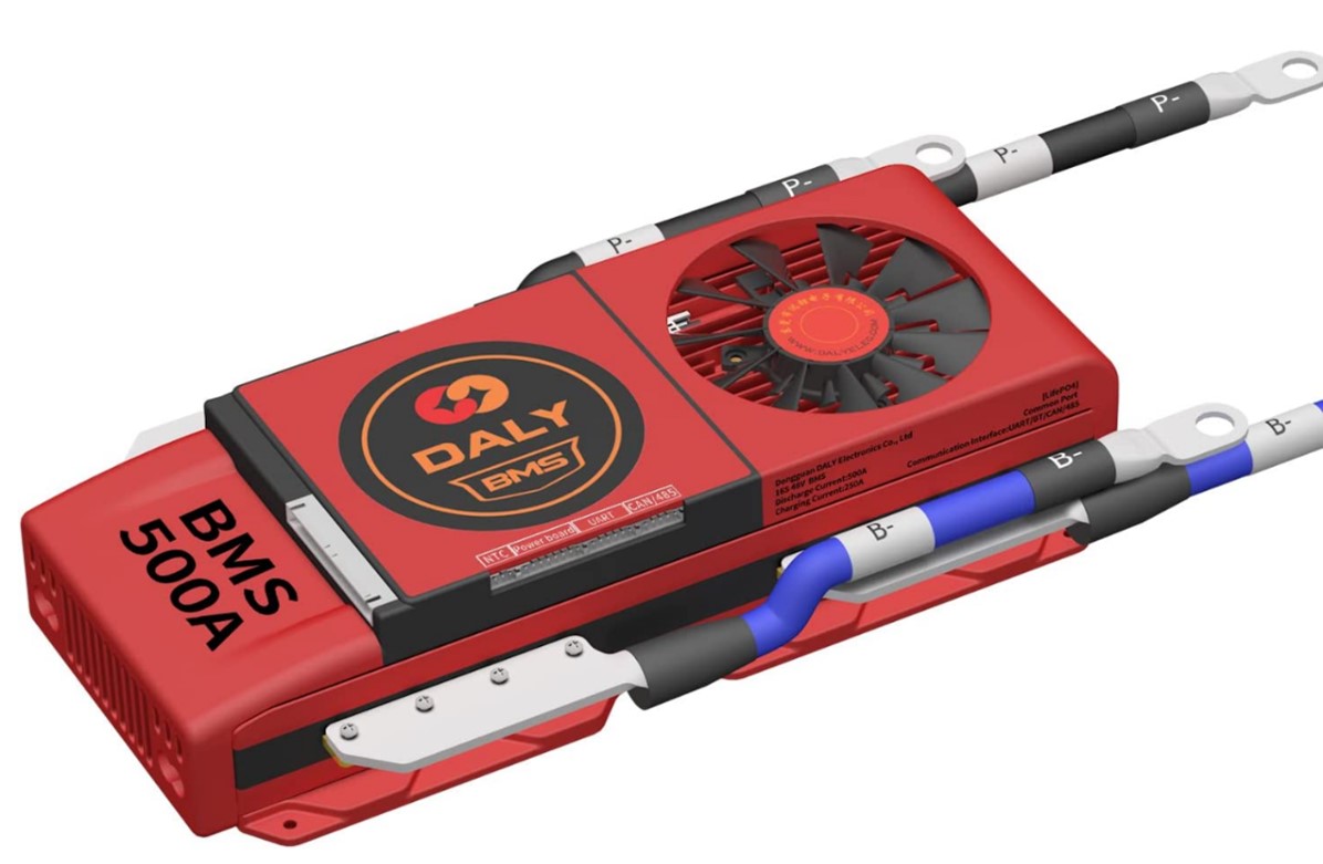
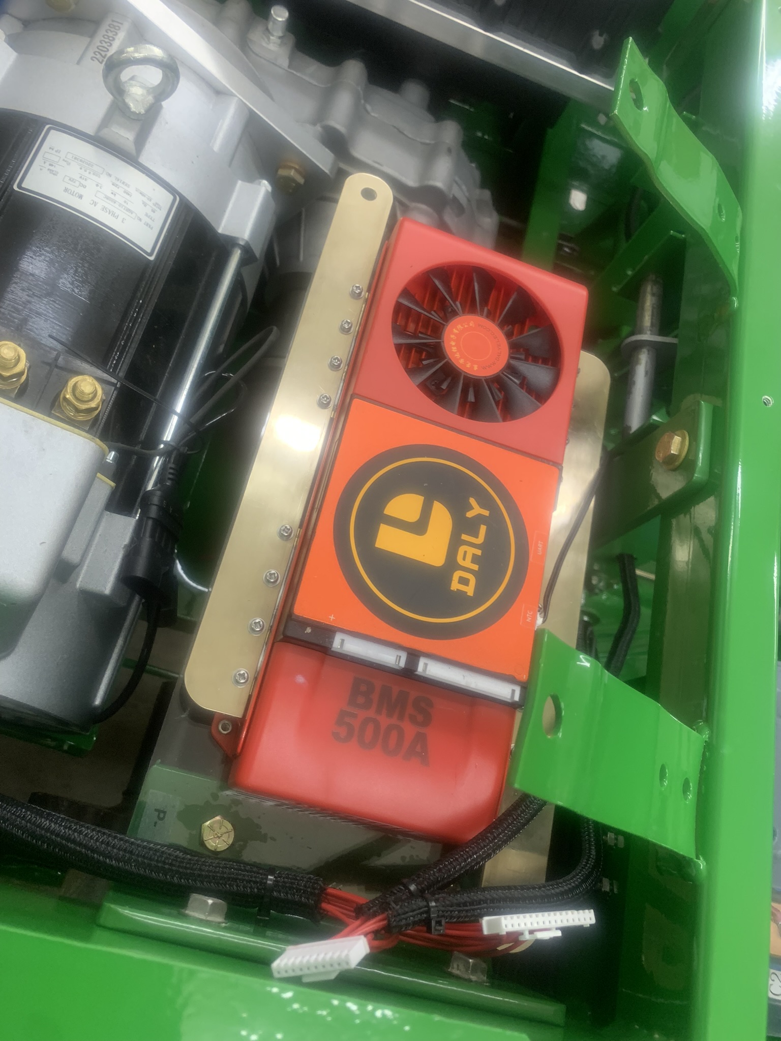
This is like a big switch connected in series with the batteries. It has sense wires that connect to each cell, and it monitors to ensure that they are reasonably balanced. If not, it can it can slowly balance them when not in use through the sense wires. In addition, it monitors voltage to make sure that they dont get overcharged (or over discharged), and shuts things down if need be. Finally, it has a temperature probe so that if it senses overheating it can shut things down. I had to find one that accommodated 22 cells (22s in BMS parlance) and 72v. I chose a Daly 500A BMS. This one has a blue-tooth interface for configuration on your phone well see how using it goes later on.
If youre curious, the main package of parts was about $1,300 dollars plus a fairly significant shipping charge. The BMS was about $300 in addition, and the charger a couple hundred more. The batteries would be a couple thousand bucks at list, but Ive seen more modern ones advertised for less. I got mine very inexpensively on Craigslist. This conversion isnt cheap, but then a new Gator is about twenty grand, and this conversion/rebuild is going to be a fraction of that cost. Of course, if it doesnt work no telling what I can do with it and all will be lost. Ill keep my fingers crossed that it will work.
After what seemed like forever, the crate with the main goodies arrived
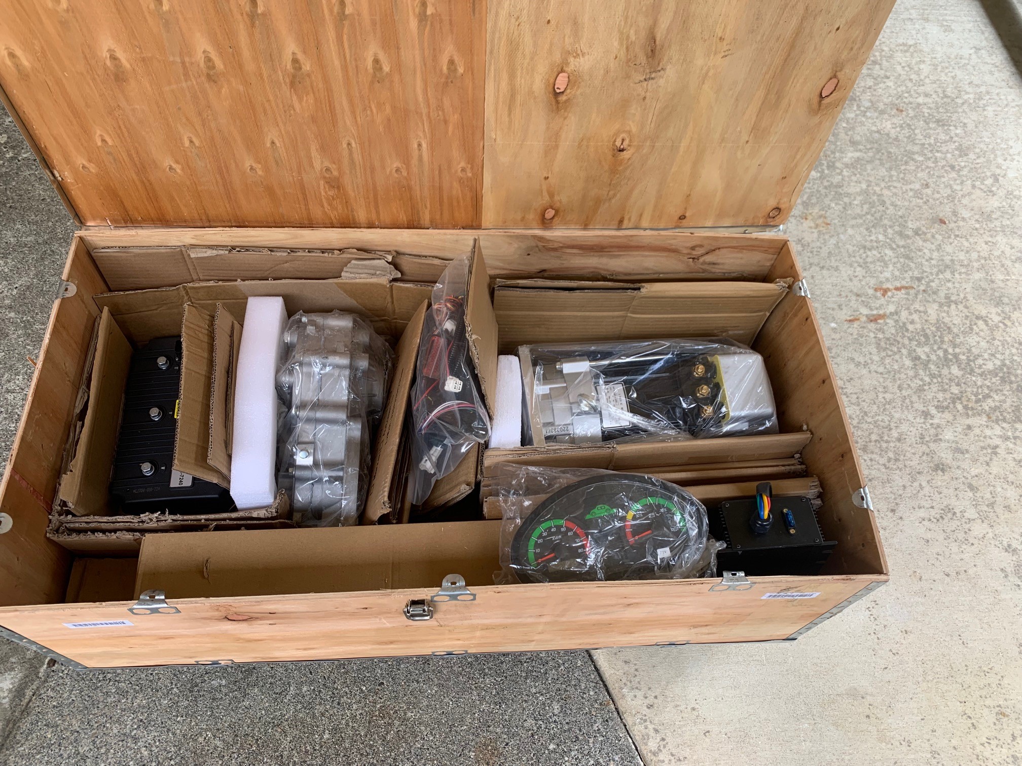
Although this will turn out to be the first of many shipments of parts as the project continues - bolts, nuts, hose, cable, brakes, new plastic body parts, steel,..
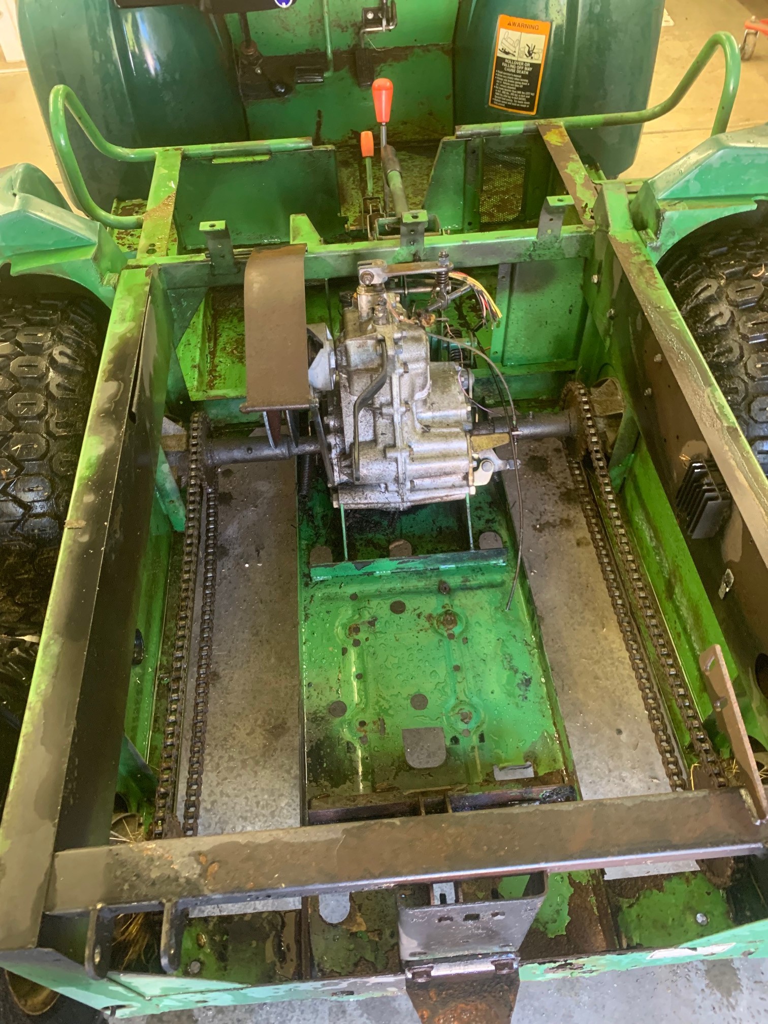
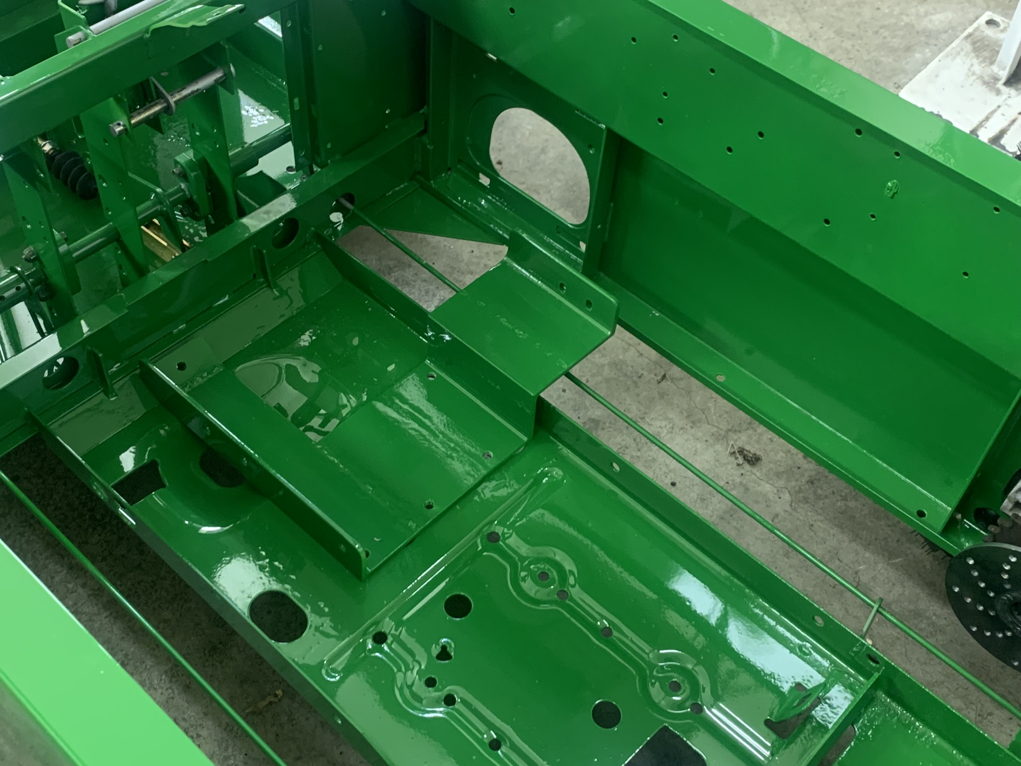
After taking out the burned-up engine and steam-cleaning things, this is what the factory drive-train looks like .
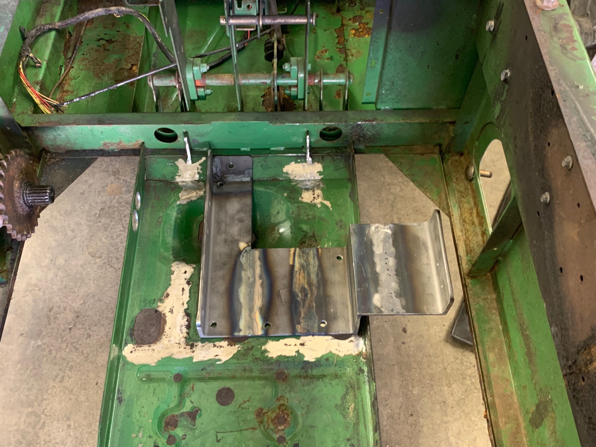
Time to remove the gearbox and front drive wheels, then cut out the original gearbox brackets. I fabricated the gearbox/motor mount out of ¼ thick steel. It's pretty tough to get all the dimensions right with no drawings of the motor and gearbox, even seprately. I'm doing CAD drawings of most of the parts I'm making, so if I have to redo down the road, it will go a lot quicker.
The Gator is half metric and half SAE, and the motor stuff all metric I never know what wrench to pick up! Wish we would join the metric world and get it over with rather than many more years of mix and match. Seems like I spend half my design time multiplying and dividing by 25.4.
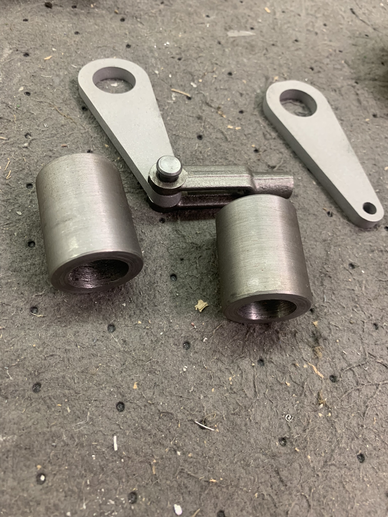
On the drivers side, I coupled one-half of the original splined adapter from the Gator (black part) with the shell of the CV joint, no room for an axle between the two. I just removed the CV parts from the shell, and drilled a 5/16" hole through it all for a grade-8 bolt to couple the shell and splined adapter (not seen in this picture, but one later on).
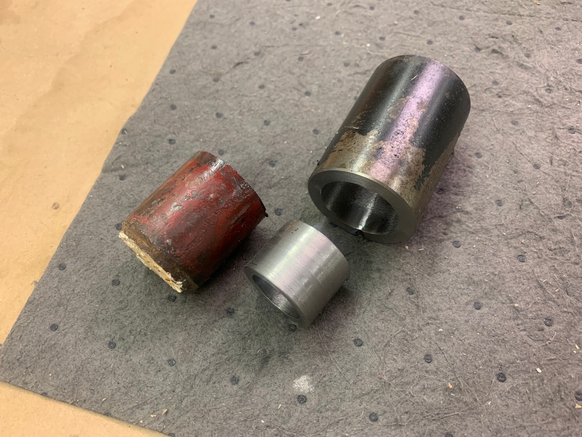
On the passenger side, I cut off the provided axle, then machined a spacer to adapt it to the black Gator splined part (black in the photo). Fun turning the red piece of scrap into the bushing. I coupled them together with a 3/16 diameter roll pin.
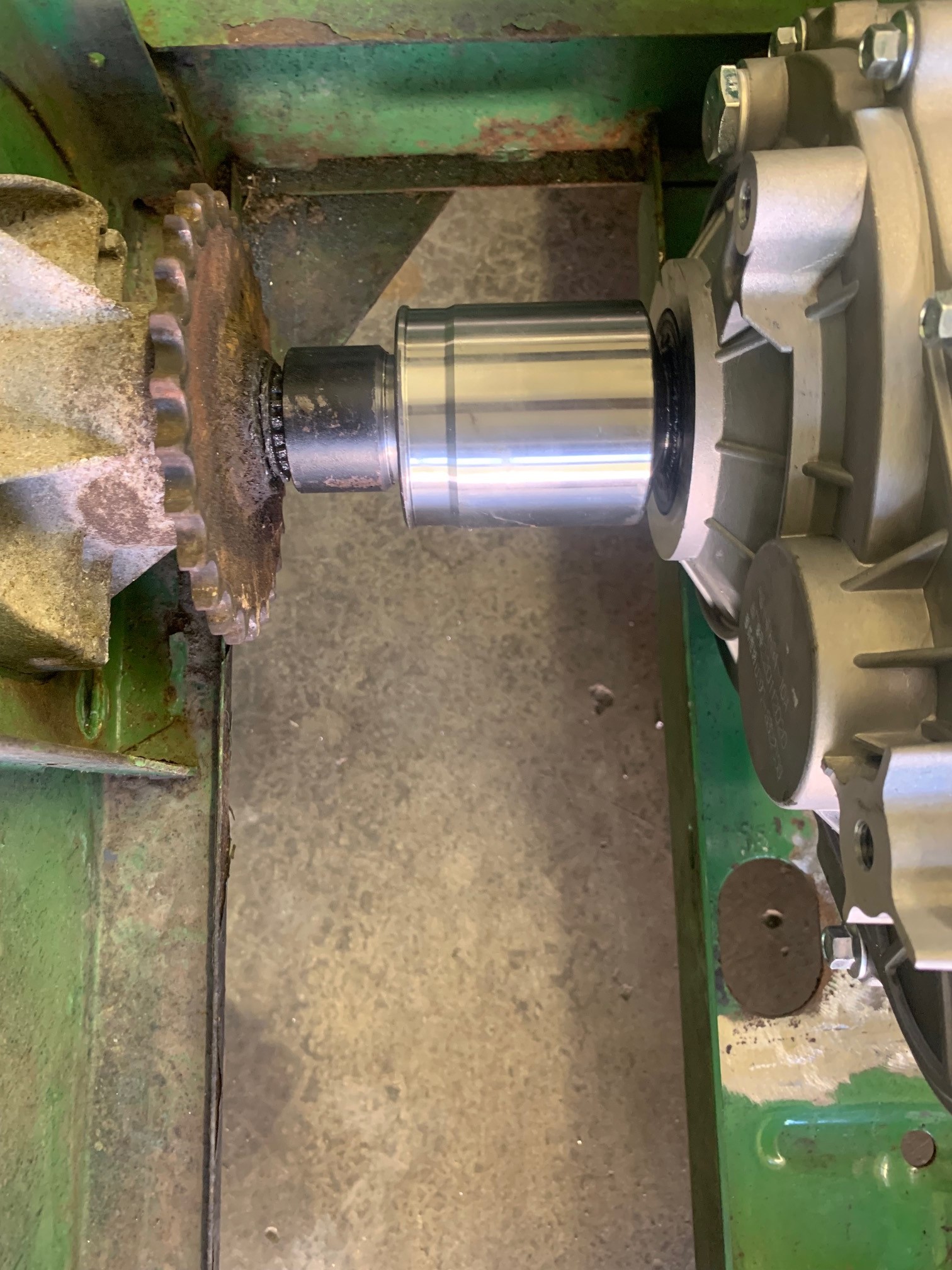
In this shot, the axle and bushing are temporarily sitting on top of the Gator splined adapter near the sprocket, but it shows how things will fit together on the passenger side where there is lots of room for an axle and CV joint.
As I mentioned, the original gearbox had brakes built in. But now I have none. I thought that I might be able to mount brakes on the front drive-axles, but there just isnt room. So, I decided to put some disk brakes on the rear axles. I went with mechanical rather than hydraulic since at some point I might want to add separate brake control like tractors with two brake pedals, so you can help with steering or slow down the slipping wheel so the other wheel gets power when you are stuck. Not that I think weve ever found that necessary hard to get stuck with a 6x4 with wide traction tires. In addition, these dont really like to turn even when not locked, let alone when locked you just have to plan on going mostly straight.
I bought a couple of mechanical brake calipers intended for a go-kart. I'm thinking that if one of these stops a kart (they use one since it's solid axle), two should stop a Gator.
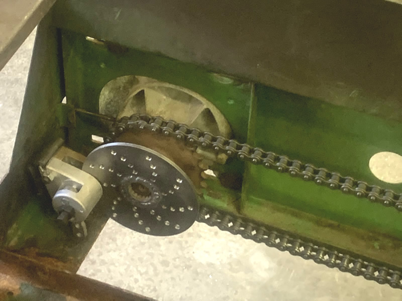
I made the disks from some scrap steel, had to drill them to look racy, and make different left and right ones so the pattern was going the right direction on each side - might lose points at a concours otherwise. ;-) I machined the Gator splined hub adapters (after cutting them in half) to accommodate these, and welded them together. Had to anneal the adapters before I could drill and tap a set-screw hole. If the new roller chain ever needs adjusting, I might have to shave down the spacer blocks or disks, not a perfect design, but I think Ive only needed to adjust the chains once in all these years, and Im starting with new ones now. In this picture, I haven't bolted in the calipers yet, or installed the brake rods, but you can see the lever where they will attach.
Up front, I made some parts to extend the original Gator brake actuator rod and add a lever arm that connects to the rear via a ¼ diameter rod (see above). I purchased the clevis at McMaster, made the rest of the parts.
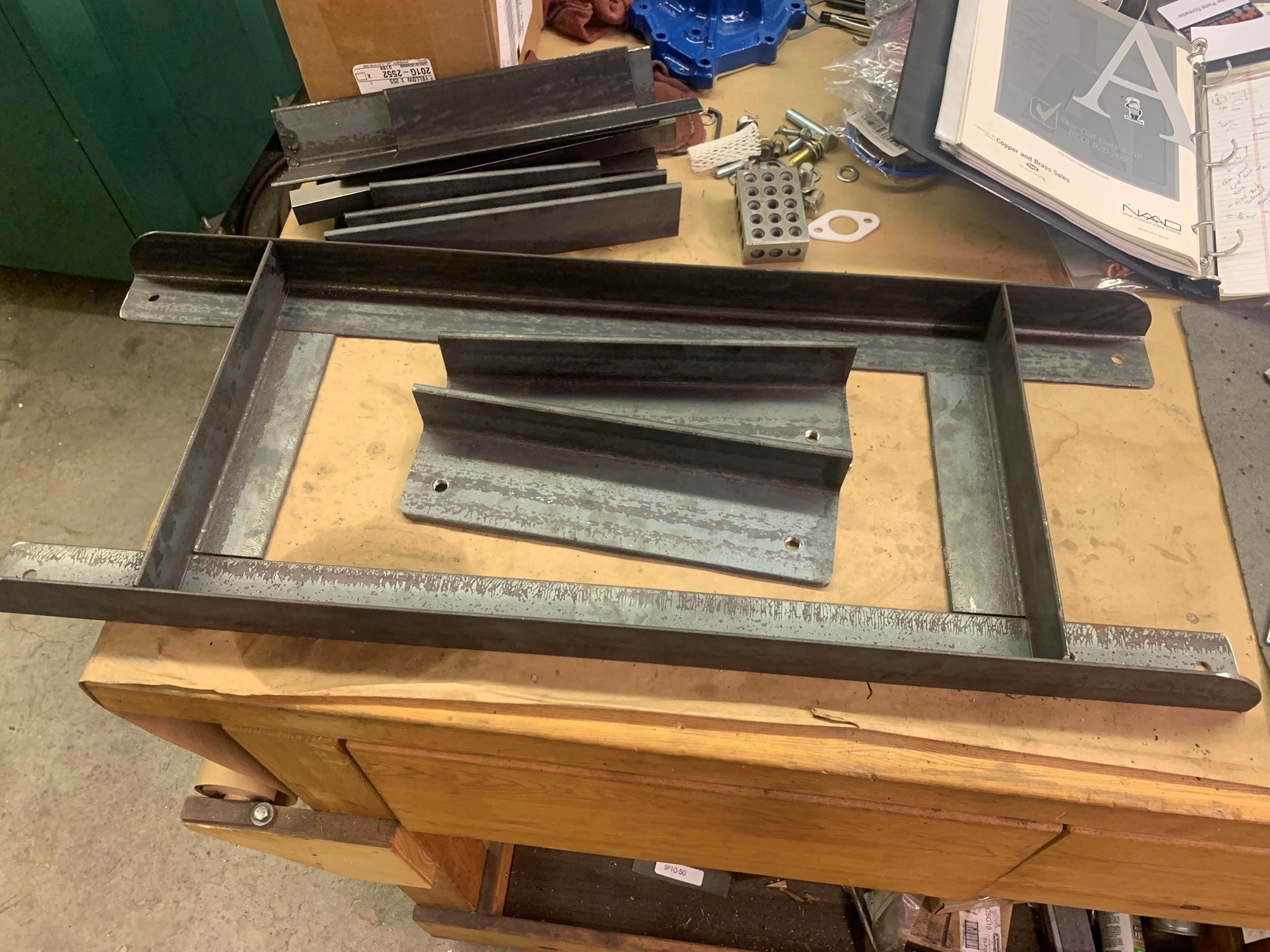
Time to make battery mounts. Heres the rear one in fabrication it bolts to the motor tray, and also to the outer chassis walls to tie them all together for strength.
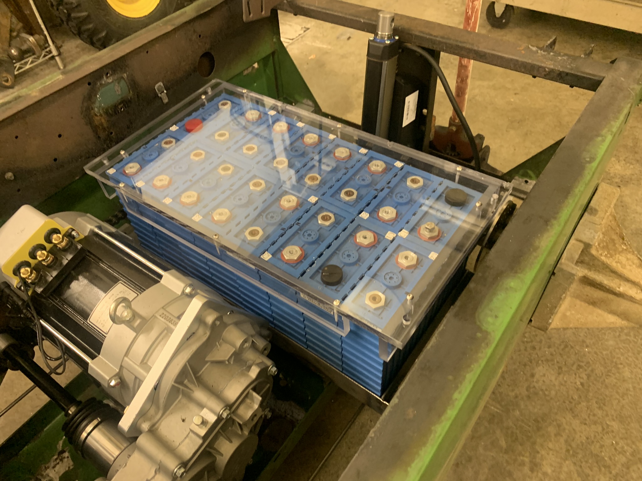
Here are the rear batteries temporarily in place. In the end, I plan to use some 1/8" rubber below the batteries and around the edges.
I had some 1/2"-thick polycarbonate stock (Lexan) sitting around, so I made battery covers. Not only to hold the batteries down, but to prevent electric shocks or something falling on the batteries to cause a short.
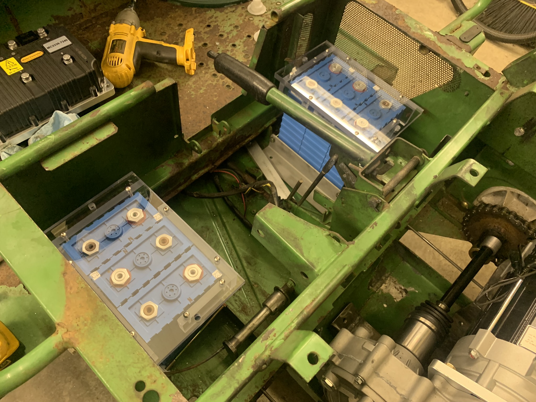
Then on to the front batteries...
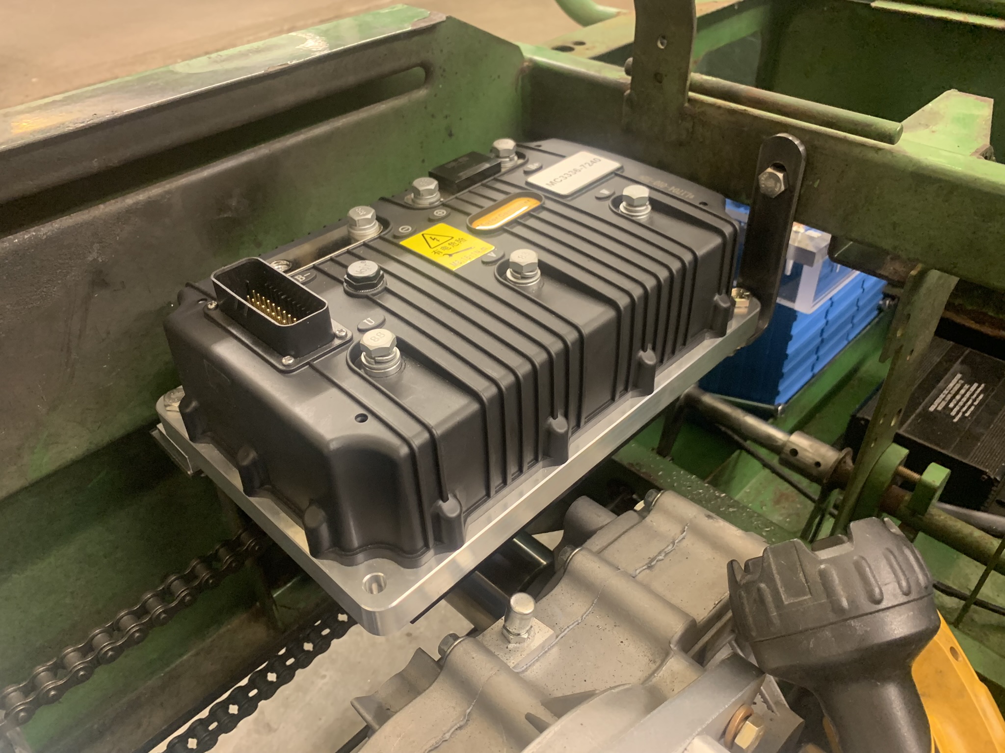
Here's the mounting for the controller - fastens to top axle housing bolts and front cross-member.
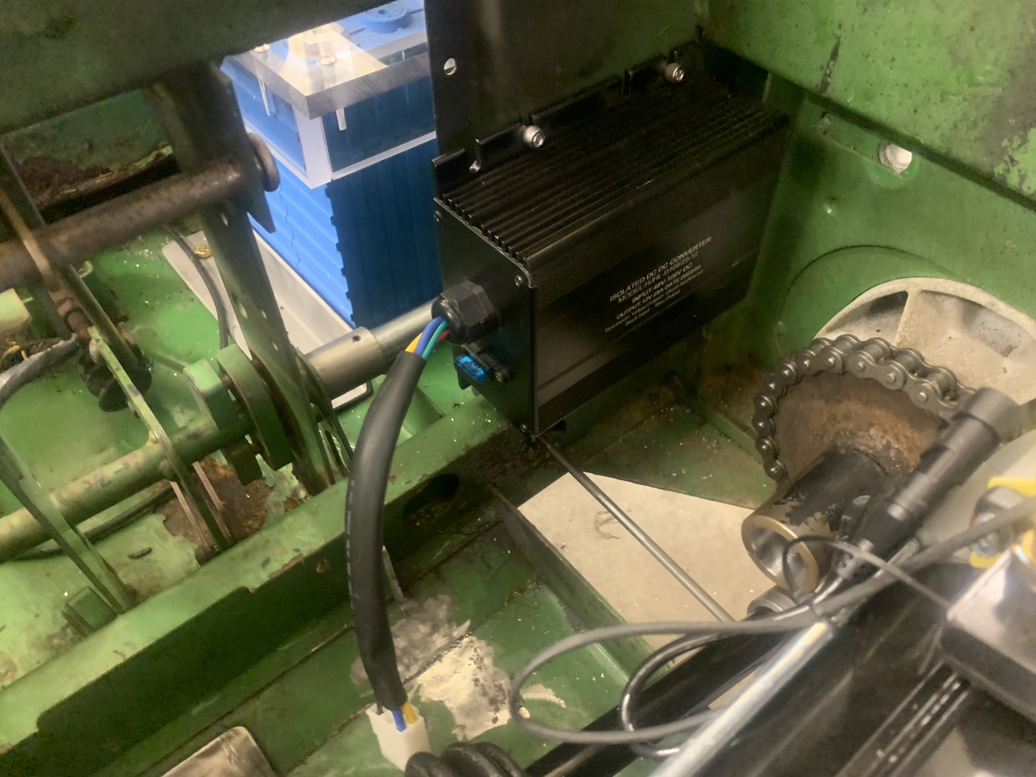
I put the DC:DC converter here, behind and below the passenger seat...
. 
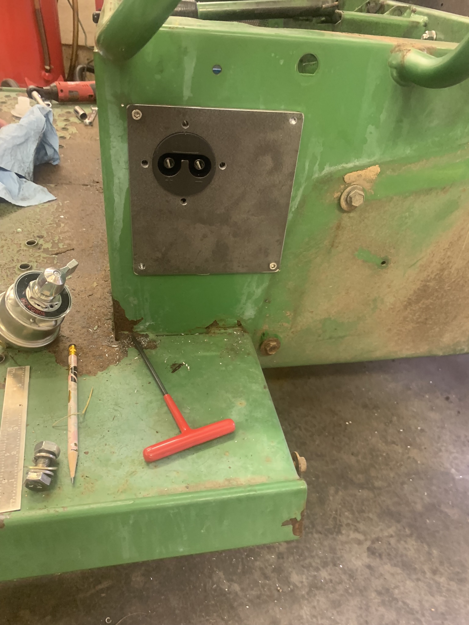
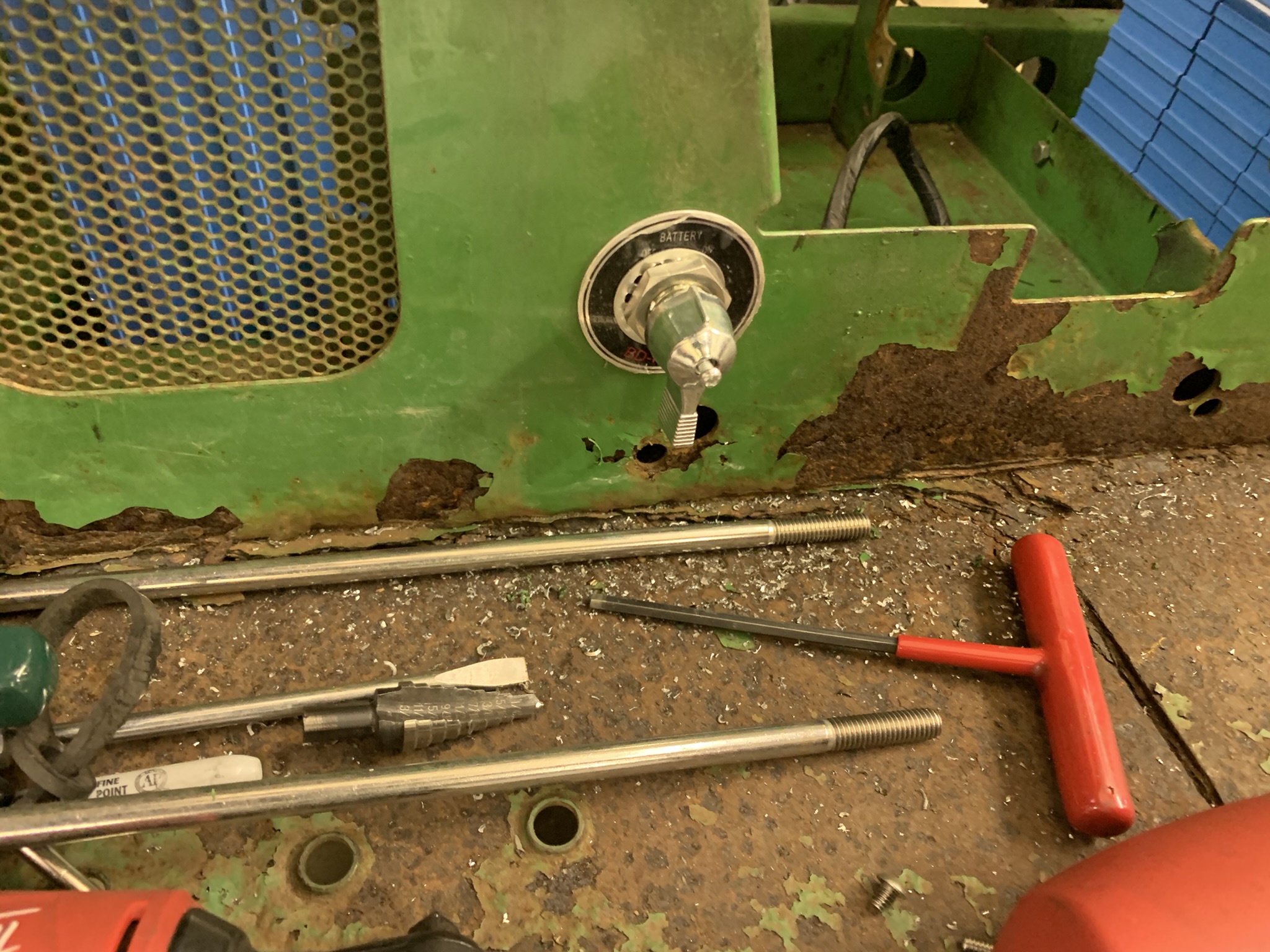
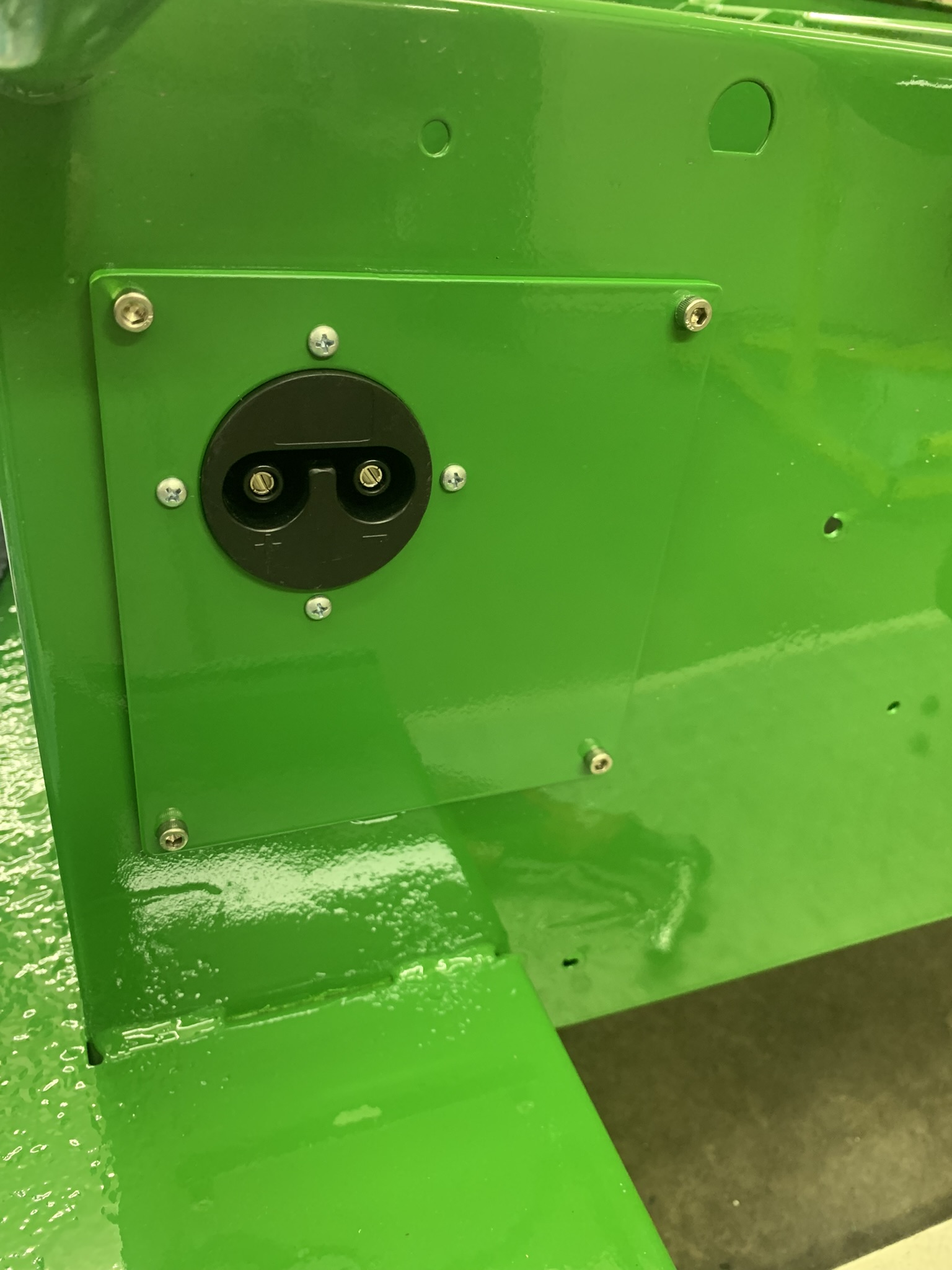
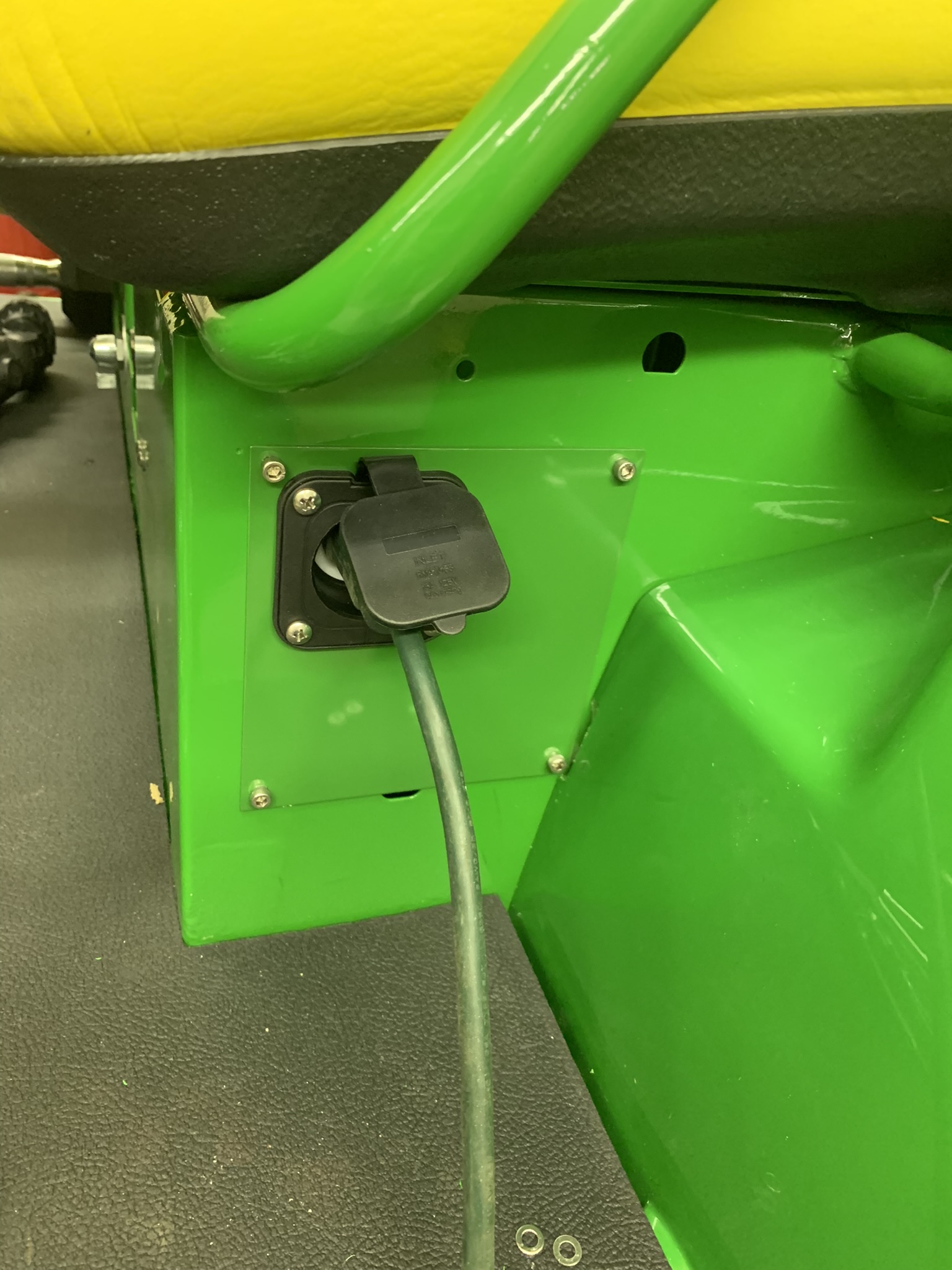
For the charger receptacle, I decided to use a Yamaha golf-cart style setup. I made this panel that mounts where the fuel filler used to come out.
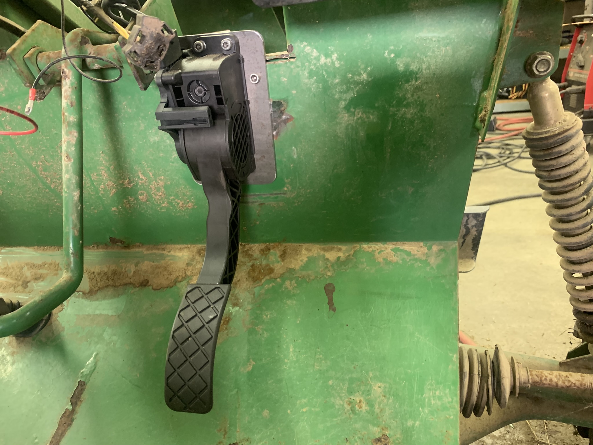
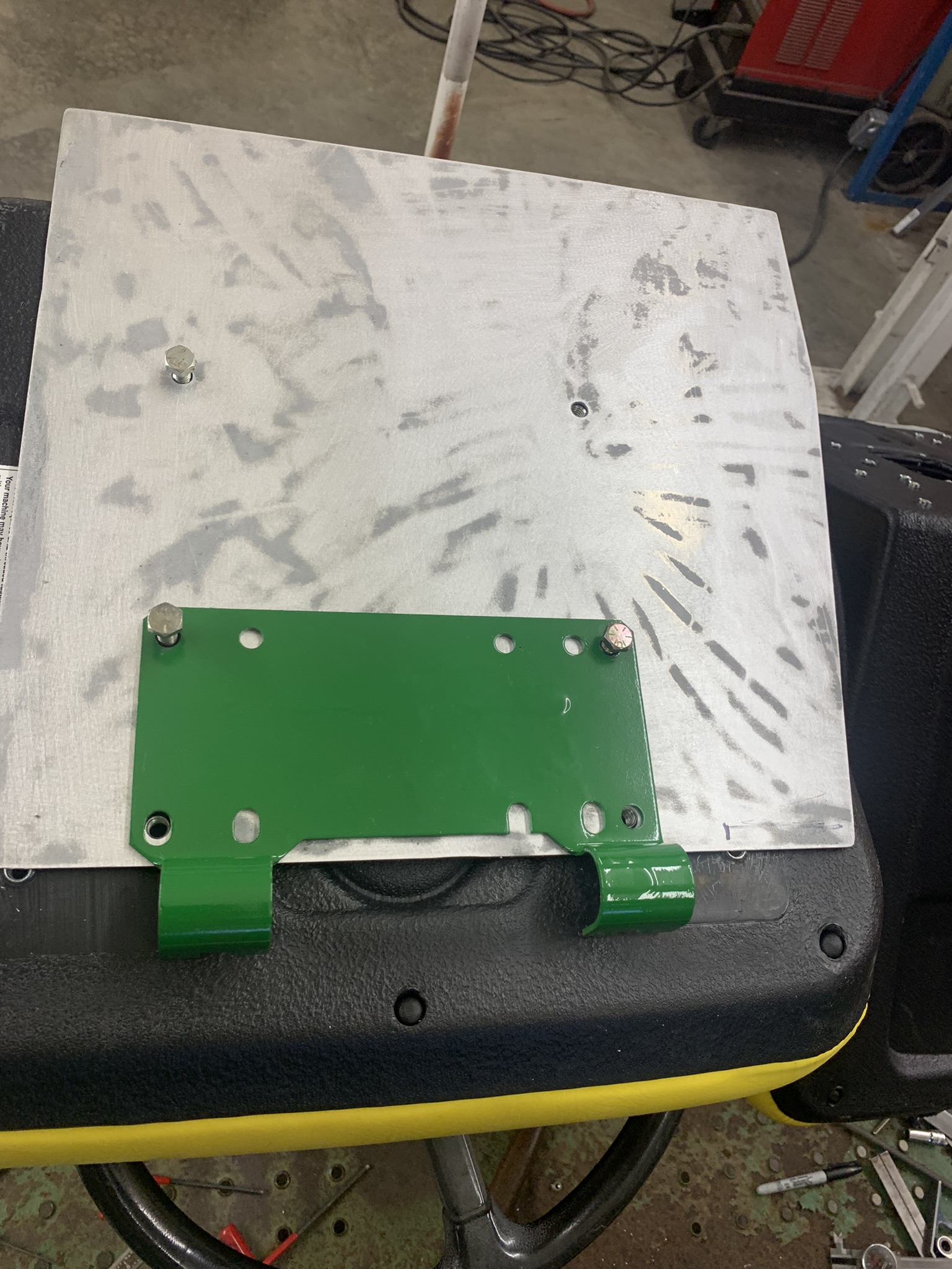
Heres the bracket for mounting the gas pedal
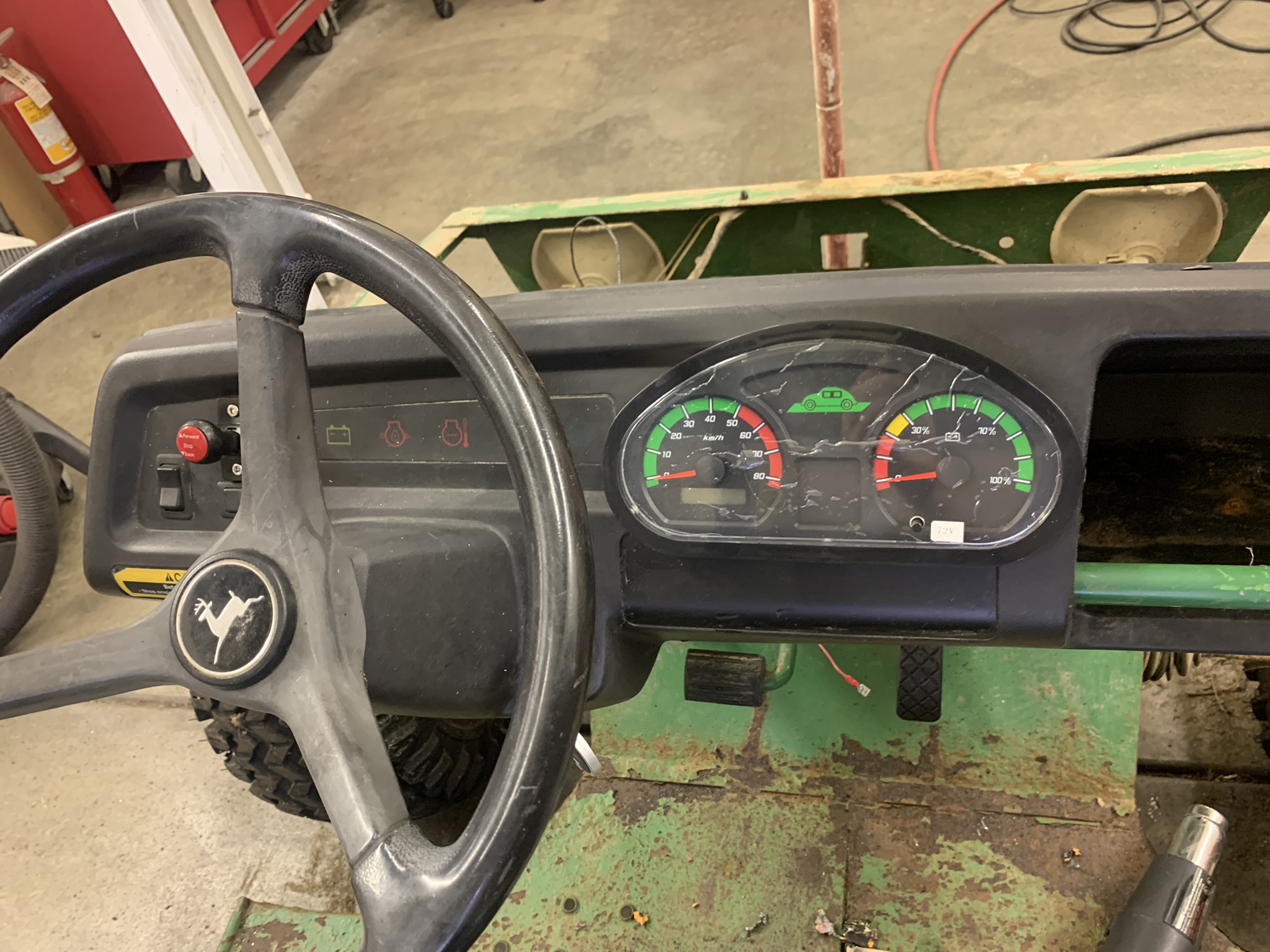
Instrument panel the forward/stop/reverse switch is shown in red towards the left. The dashboard cluster is mounted in the middle. It really isnt all crinkly like that, but I want to wait to take off the protective coating. Later on, I plan to 3D-print a black filler piece to the left of the cluster since the contours are way off. Ill use the old battery light to indicate when I have rear auxiliary power turned on. Also plan to reuse the park brake indicator lamp. Over-temperature and oil-pressure lights arent necessary any more.
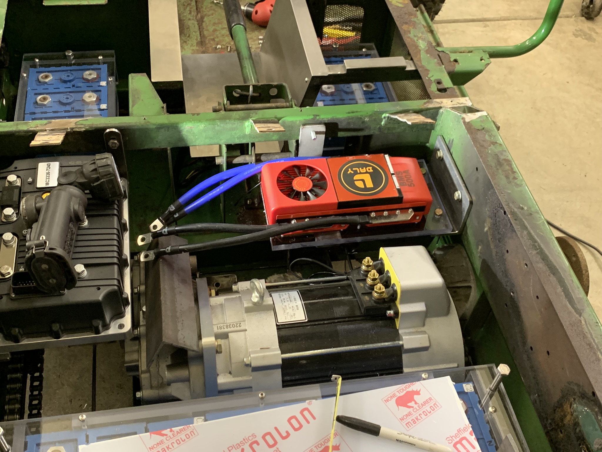
Heres the red BMS mounted above the DC:DC converter. I used some more Lexan on this mount along with some steel brackets.
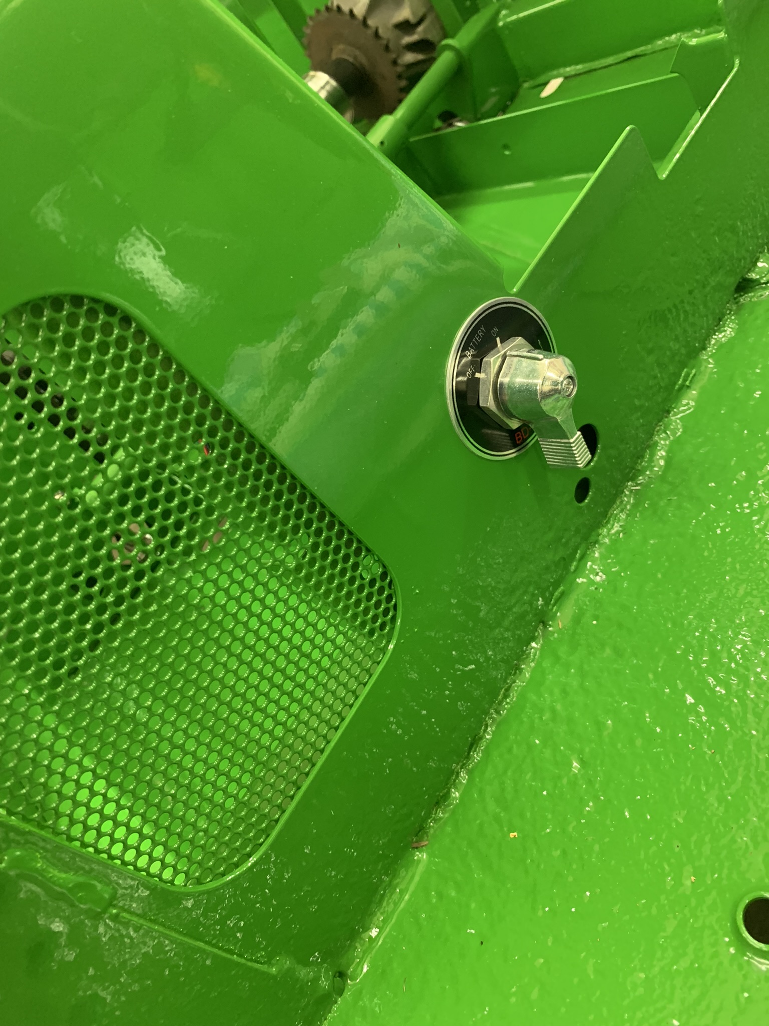
I put a main disconnect switch within the drivers reach
Covers I needed to cover the gap between the bed and seats, and between the seats. This took some sheet metal work, I had to buy a cheapo Harbor Freight brake to bend it, but it worked fine.
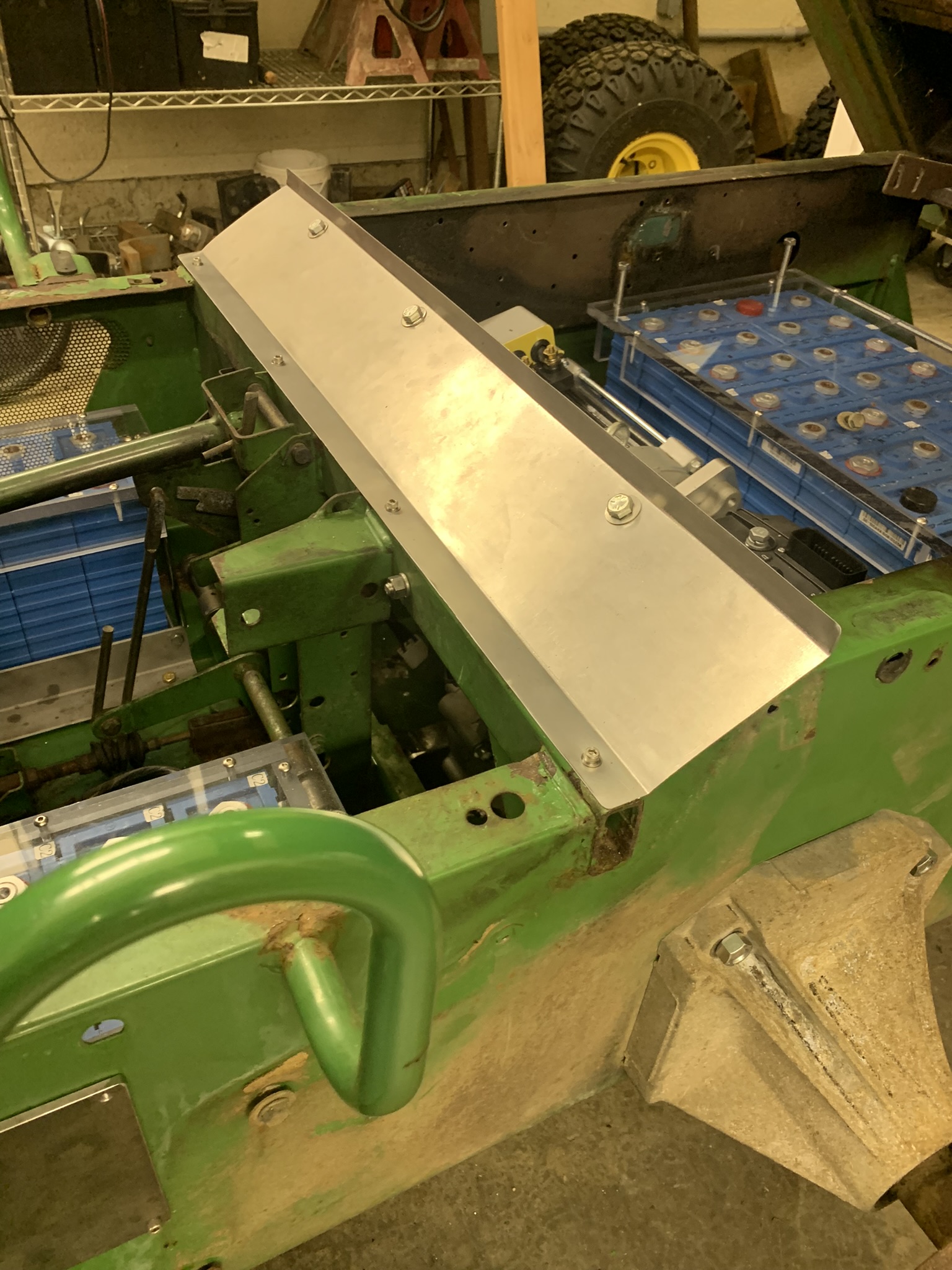
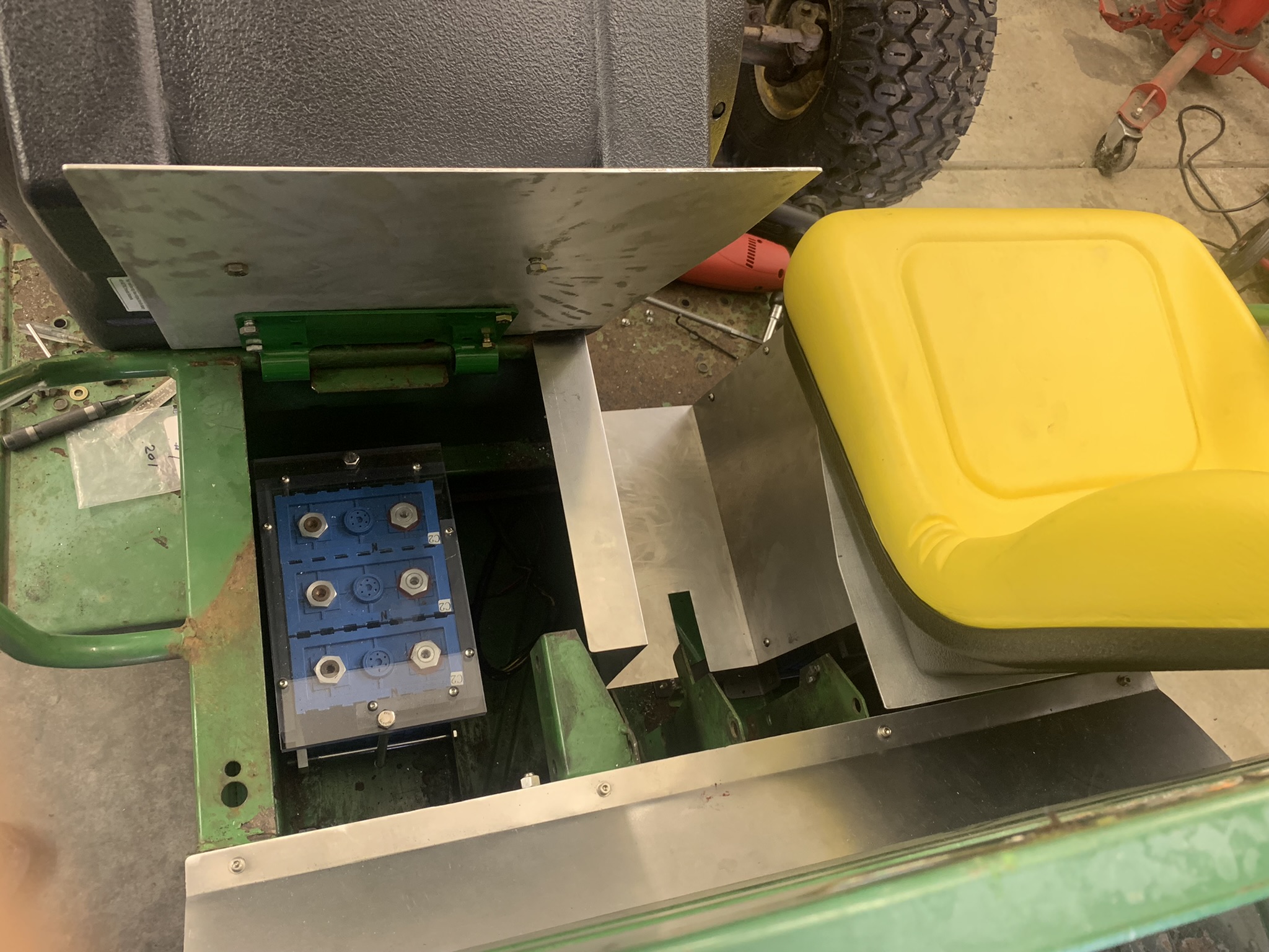
And some aluminum covers that hinge down with the seats to cover the batteries. I had bought some old road signs at the Portland swap meet that I used for this part. Not recommended! Its a real bugger to get the old paint off. But it is nice aluminum.
And finally, a cover for the brake area between the seats
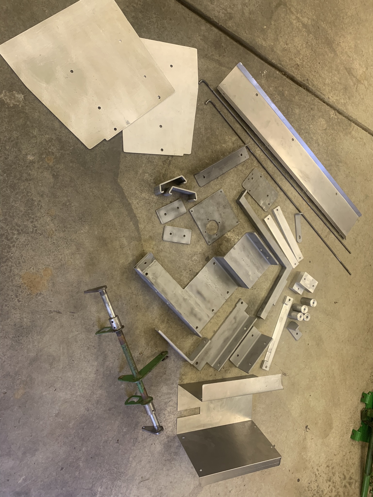
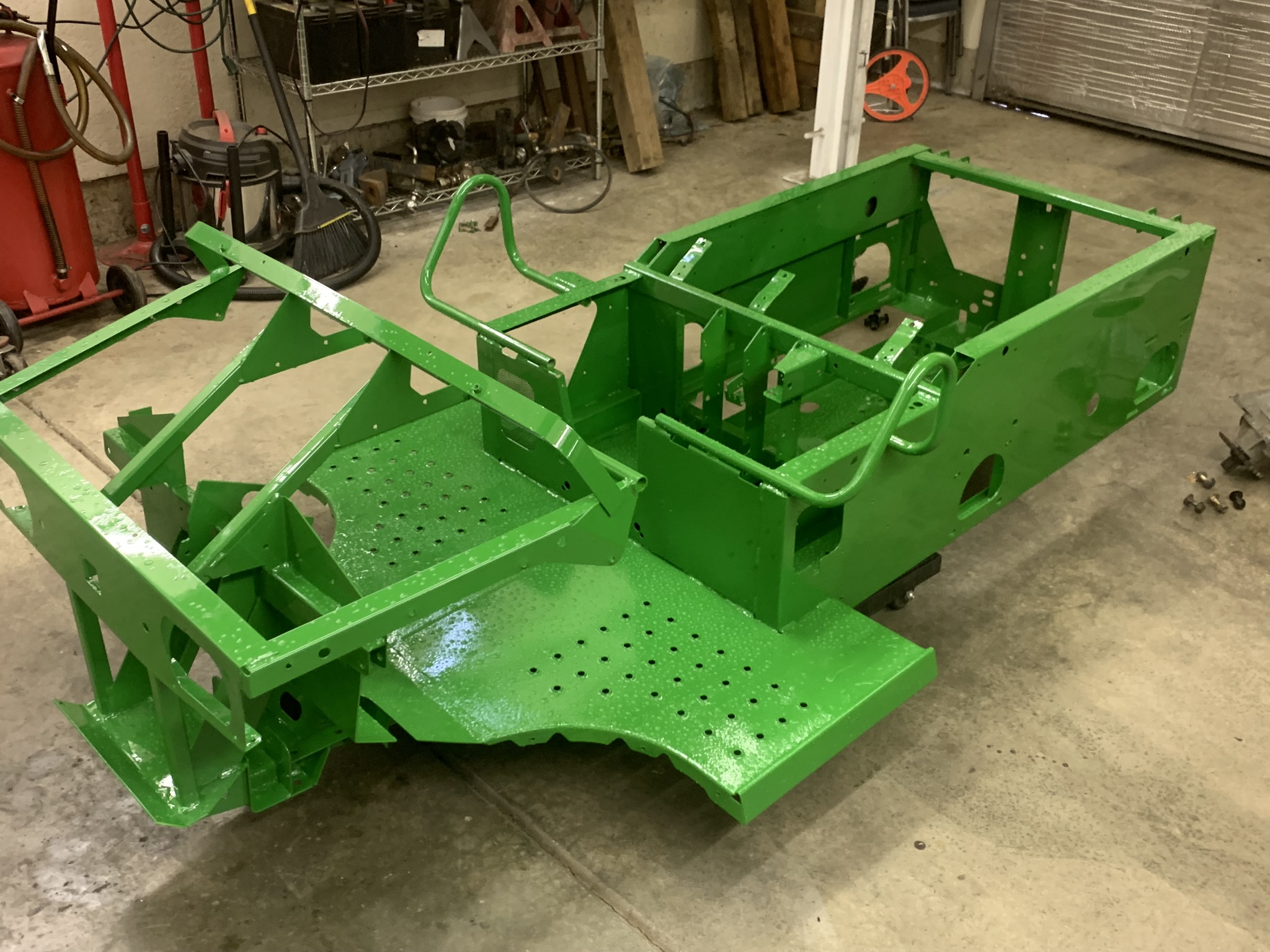
At this point, Im starting to think that Im pretty much over the hump on metal fabrication, welding and hole drilling. I'm going to take the Gator completely apart, then send it and many of the brackets Ive made off for sandblasting. I'm also going to have them put a coat of green paint on since they also have a paint booth. Ive been busy I guess here is a pile with many of the parts Ive fabricated and am sending off with the chassis. There are a few more that Ive already painted or powder-coated. Also not shown are the rear battery mount rack assembly and the Lexan parts I've fabricated...
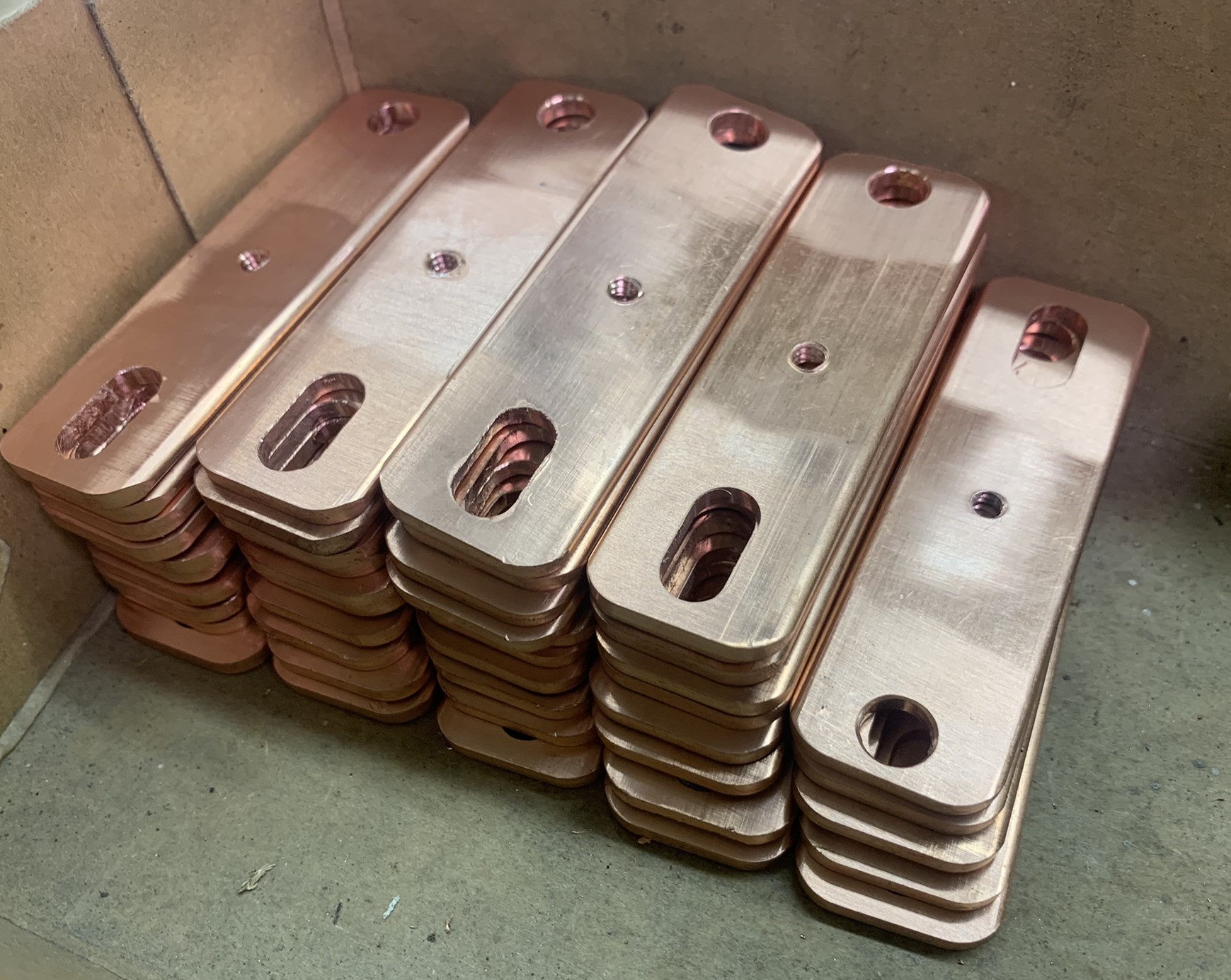
While its off being prettied up, I decided it was a good time to balance the batteries. This takes a while. First thing I needed to do was make some bus-bars out of copper. You can buy these, but my batteries have a little larger bolt size than is typical (8mm vs 6mm) so I decided to make them from scratch using 1/8 x 1 stock also a little cheaper that way. I made a slot on one end so any bar can be used to connect batteries end-to-end, or side-to-side. And I drilled/tapped a hole in the middle for the BMS sense wires. This little box is pretty heavy!
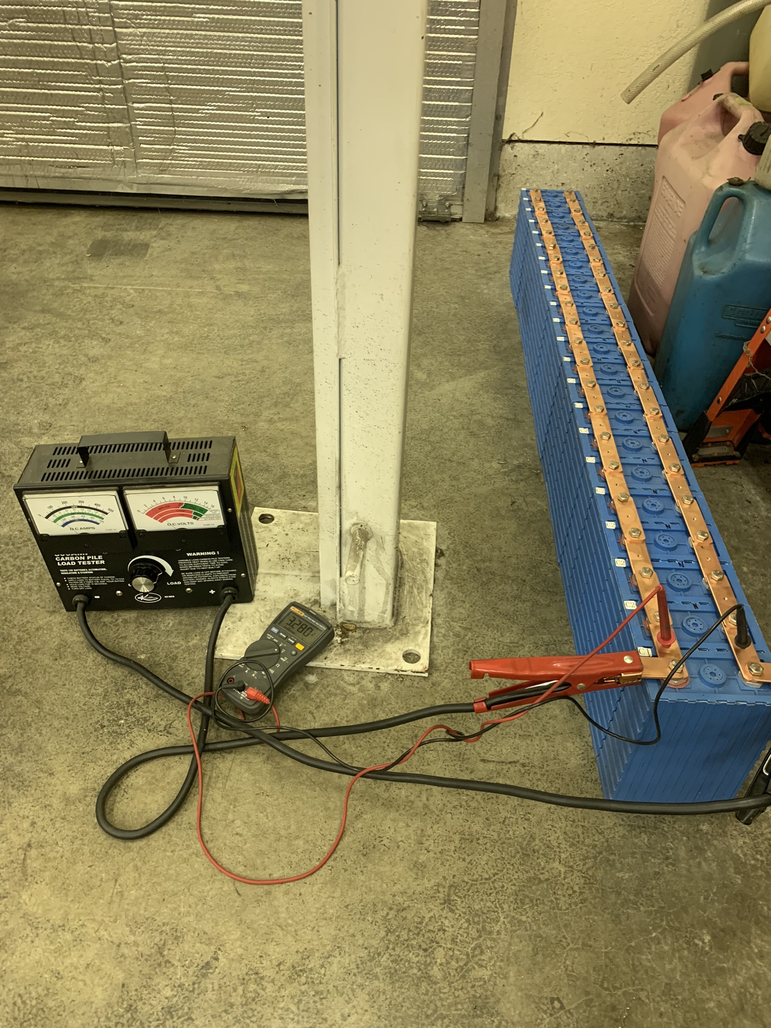
Now its time to connect all 22 cells in parallel to balance them. Kinda scary to install the bus bars since they are long enough to reach the opposite terminal and short out the battery if you arent careful (remember the 800-amp part?).
To discharge the batteries, I used a battery load tester. The best it would do at this voltage was 80-100A, so it ended up taking a day or two to discharge them. To my surprise, the bus-bar at the end (carrying all the current) got slightly warm.
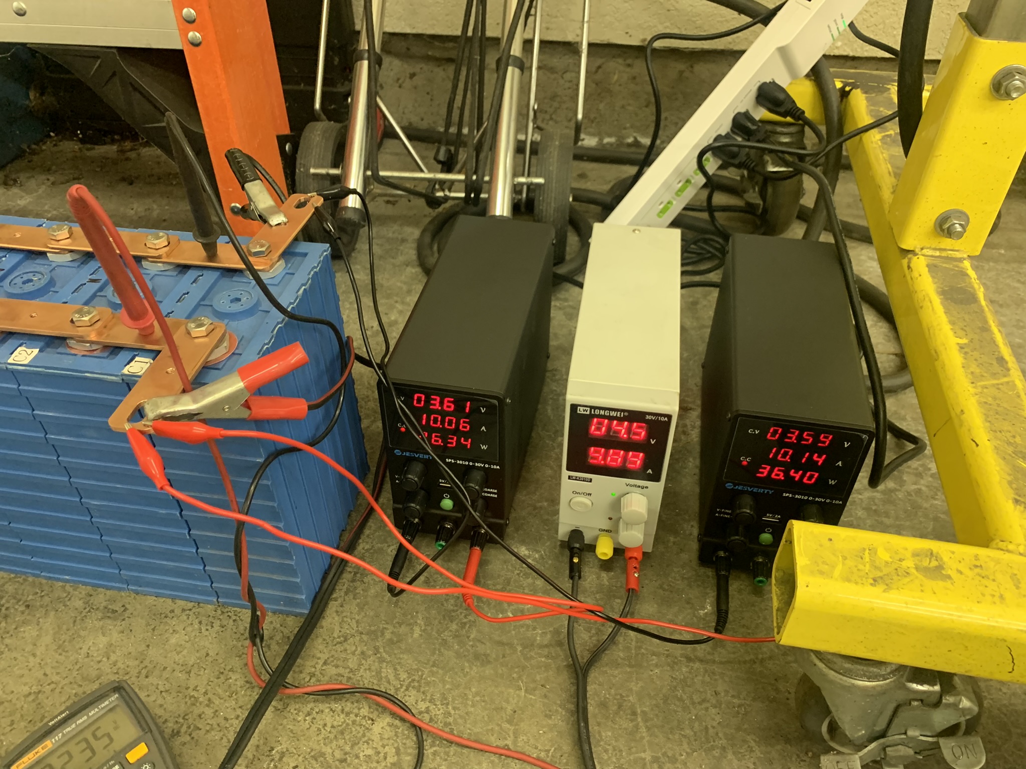
Once discharged down to about 2.5 volts, its time to charge them in parallel. I put three chargers in parallel so charging was occurring at about a 30A rate. Since theres about 2,200 amp-hours to deal with, it took 3-4 days. The "real" charger will only charge at 12A, but at 72V instead of 3.2v, so charging will be much, much faster.
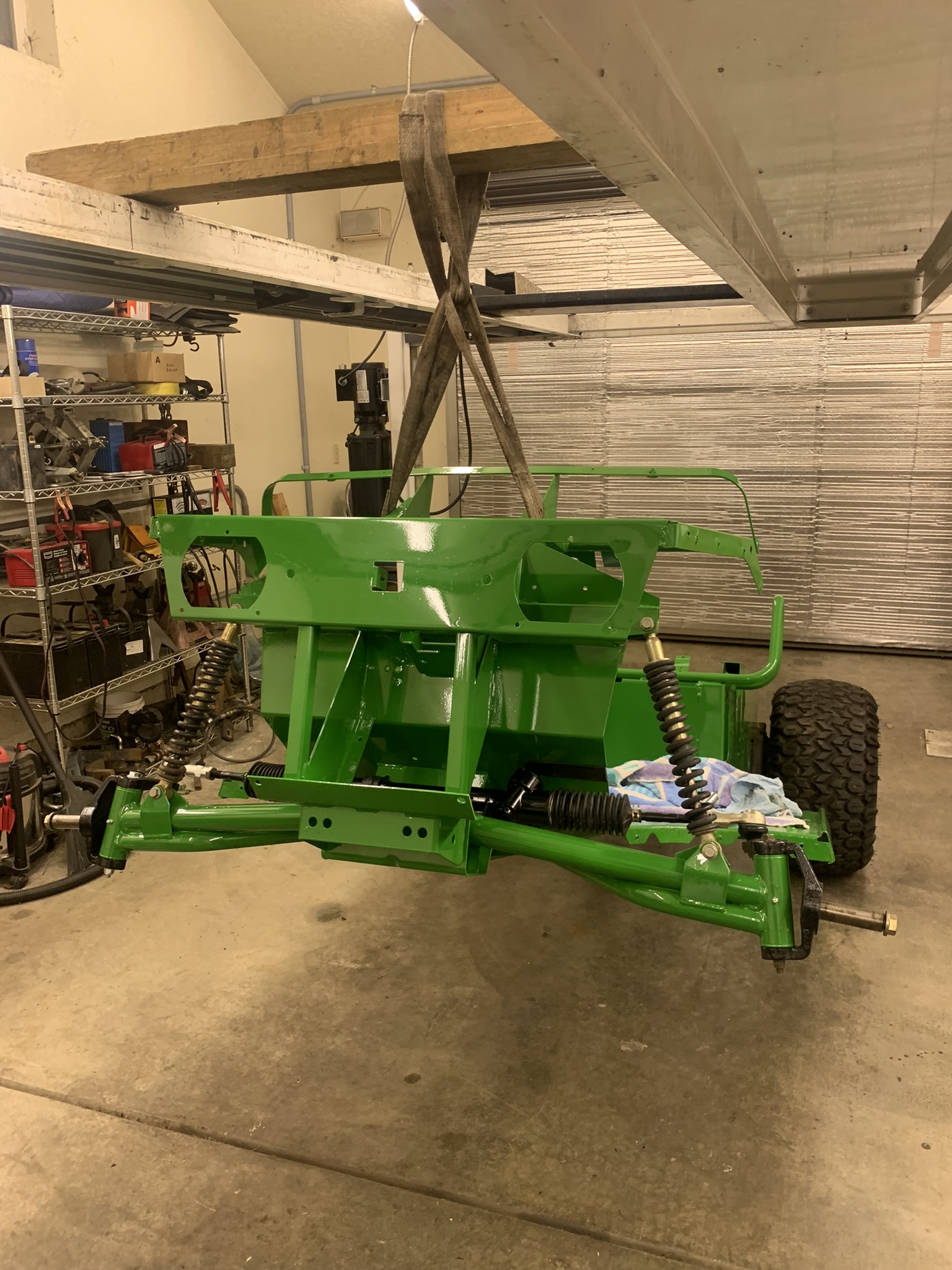
Here it is, back from the sandblast/paint what fun to deal with nice clean parts! Theres no more disassembly possible beyond this, although I missed one Tinnerman nut during disassembly. It was raining when I picked it up. so it's still all wet in this shot.
I started out by putting back all the front suspension, which I had rejuvenated while waiting. Ive used the car lift as a jack for this, and also to lift the motor/gearbox in and out of the Gator.
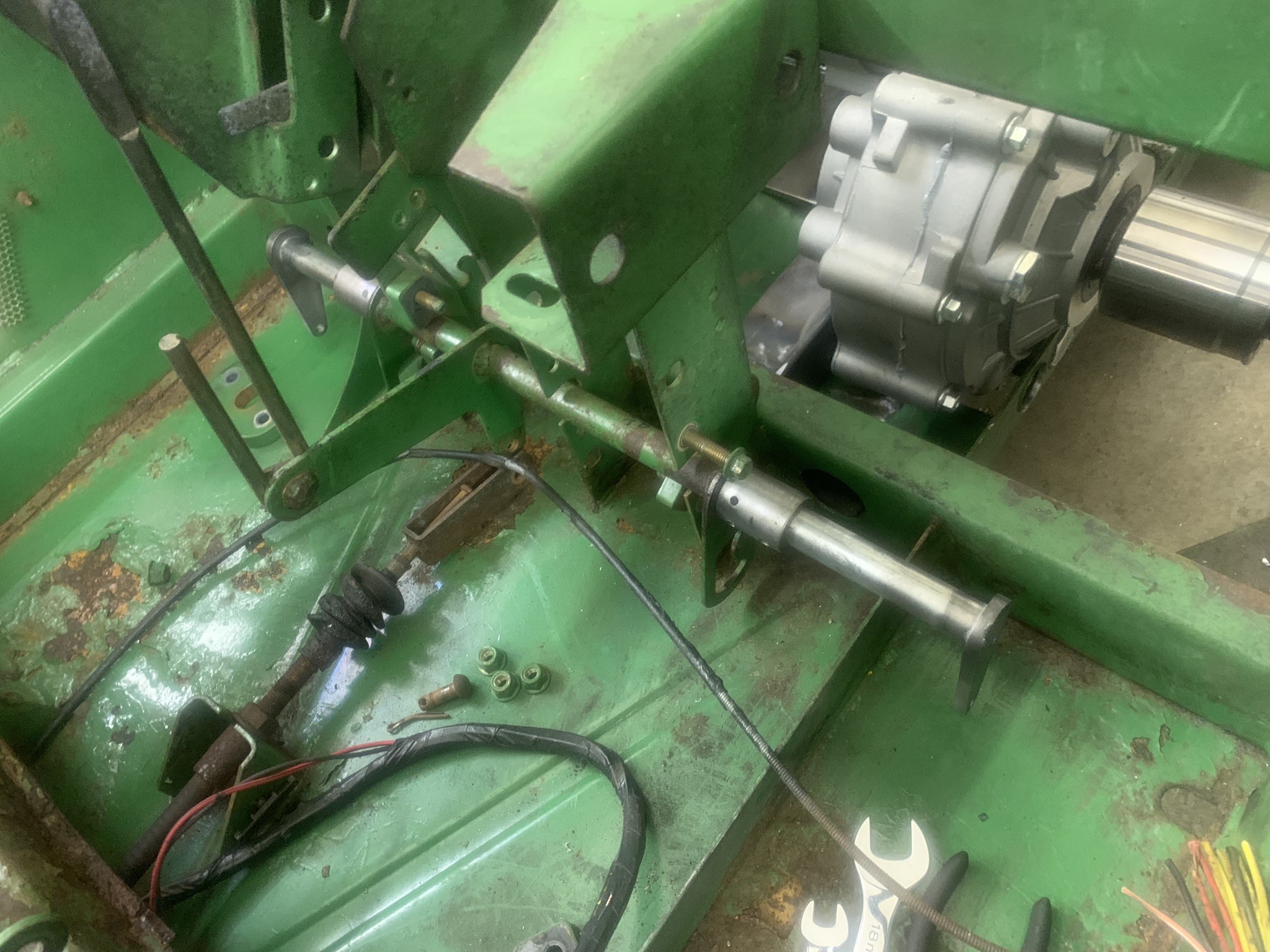
In goes the braking system. You can see where I extended the ends of the existing rod to add the new lever arms actuating the rear brakes. The extensions are a tight fit into the flanges, then secured with roll pins. You can see how the handbrake shares the same operating shaft as the foot brake, which actuates through the cable near the floor
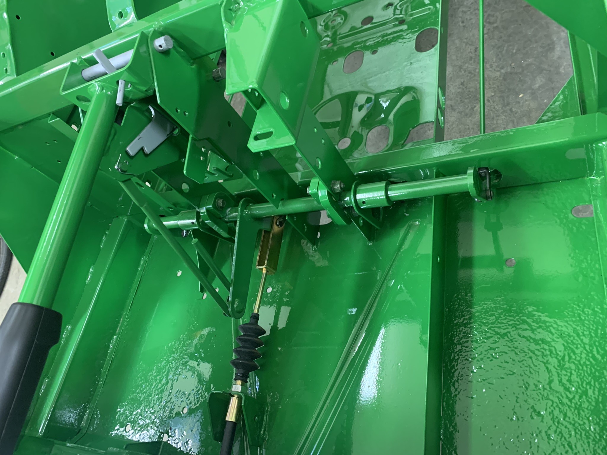
I had to add a couple of brake return springs which I hadnt anticipated.
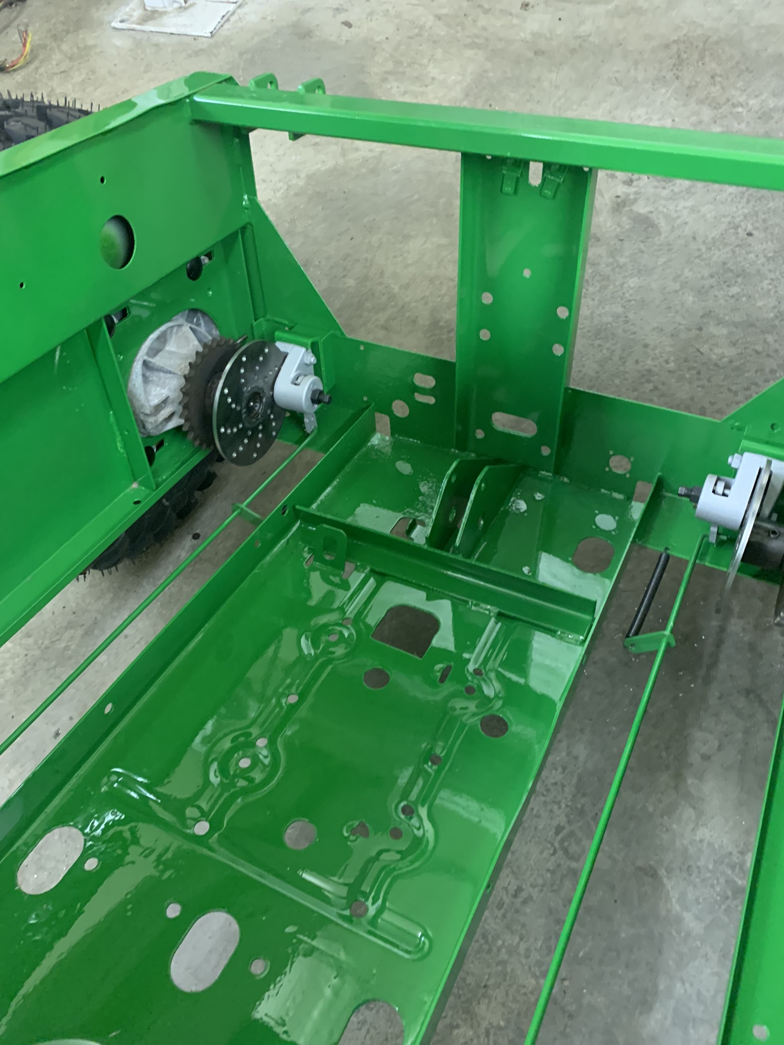
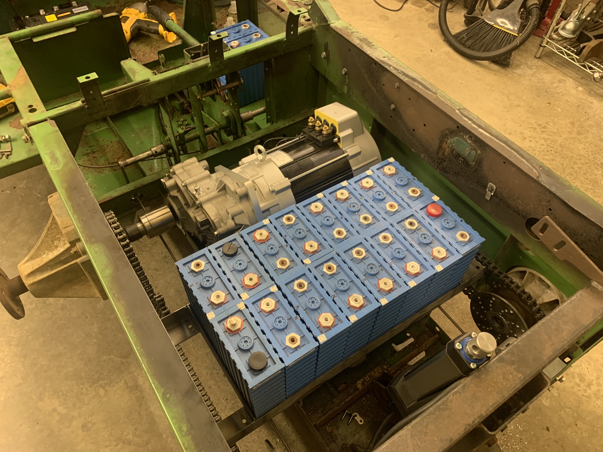
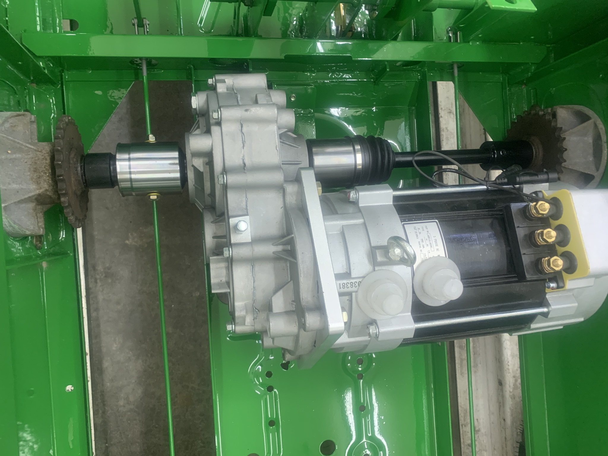
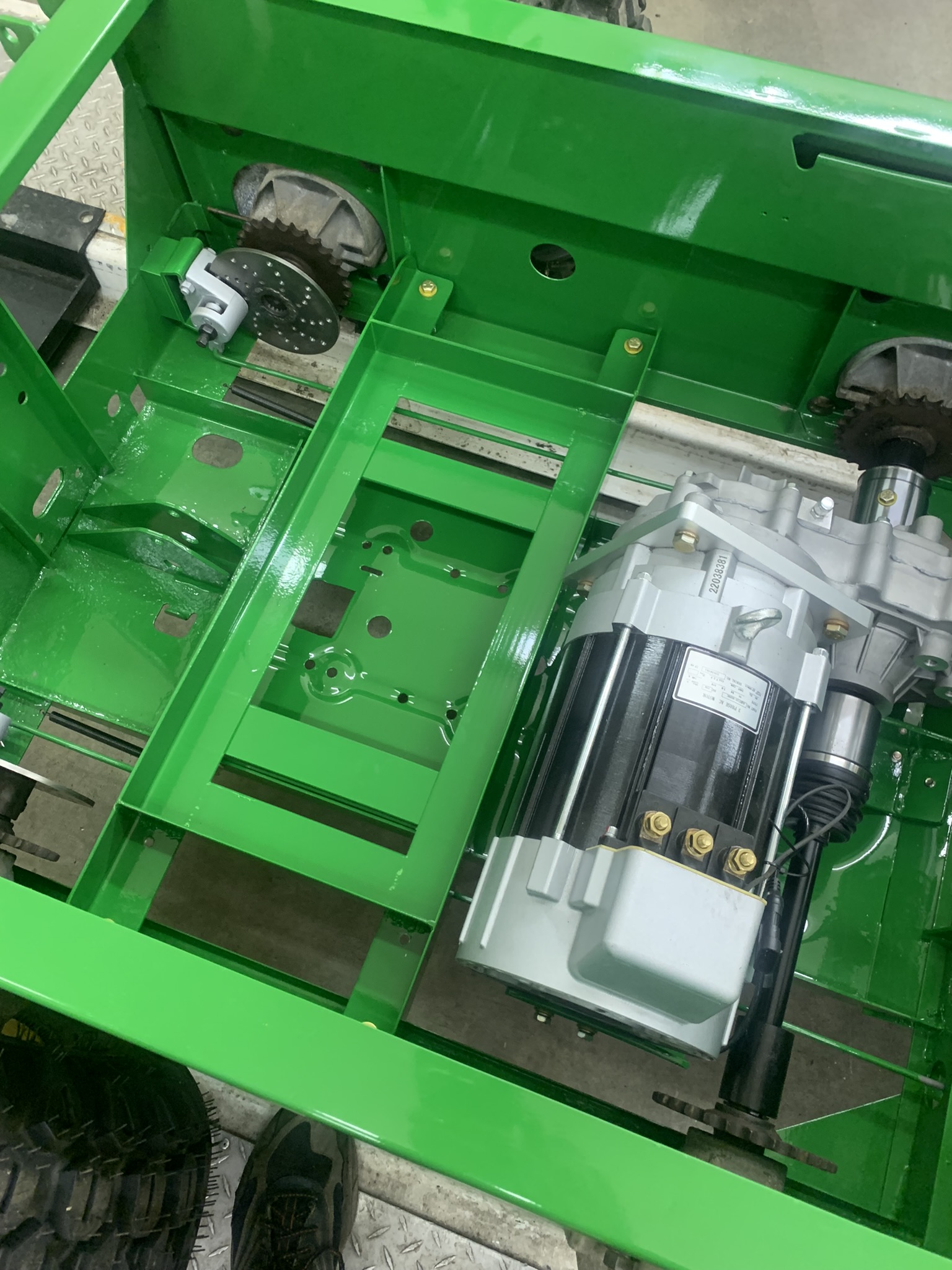
Then the motor/gearbox mount, then the motor and gearbox and axles.
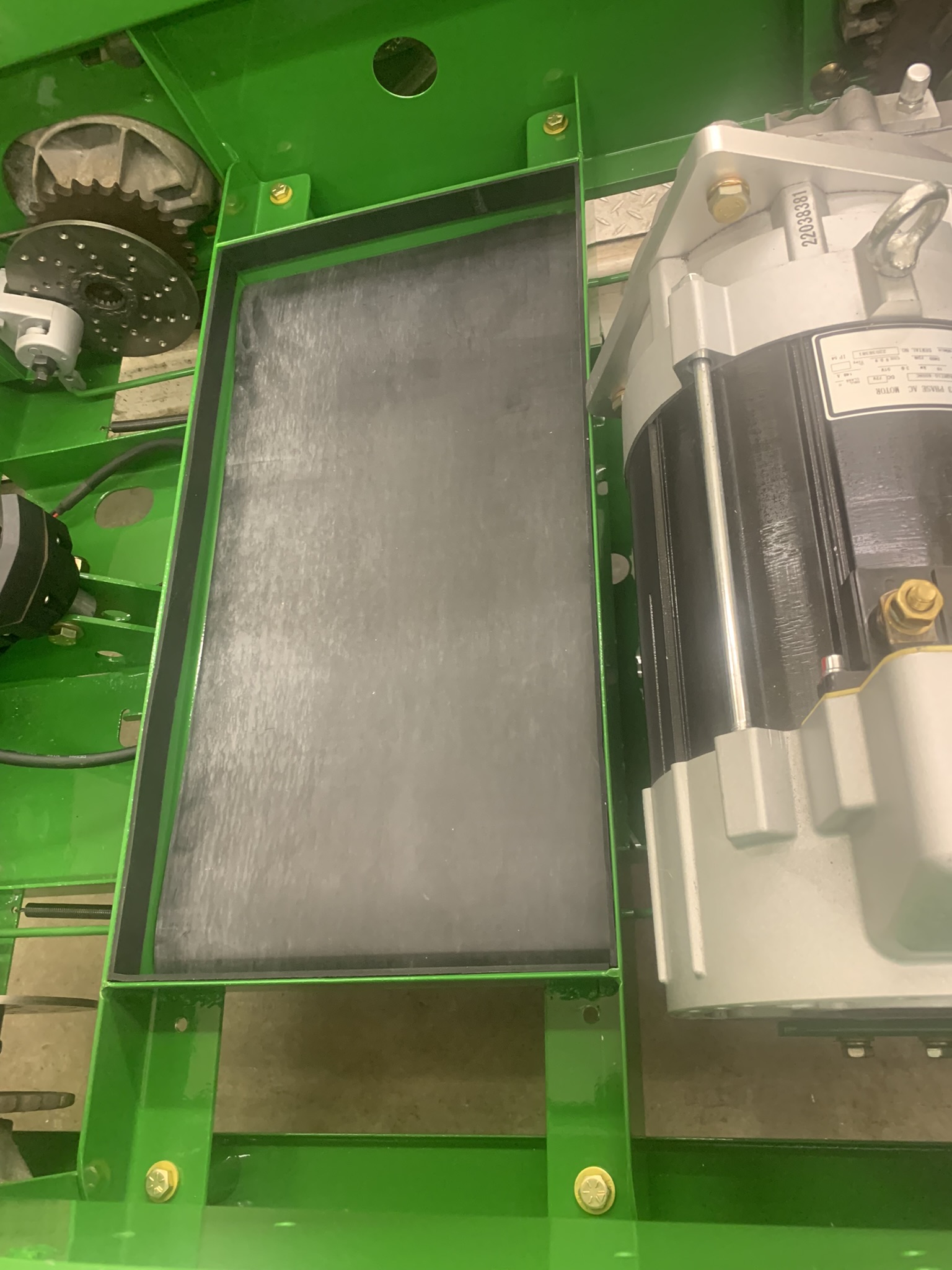
Then the rear battery mount which also braces the motor tray to the side rails of the chassis. Before I put the batteries in, I put a layer of 1/8 thick rubber below them, and around the edges (second photo).
DC:DC Converter mounted
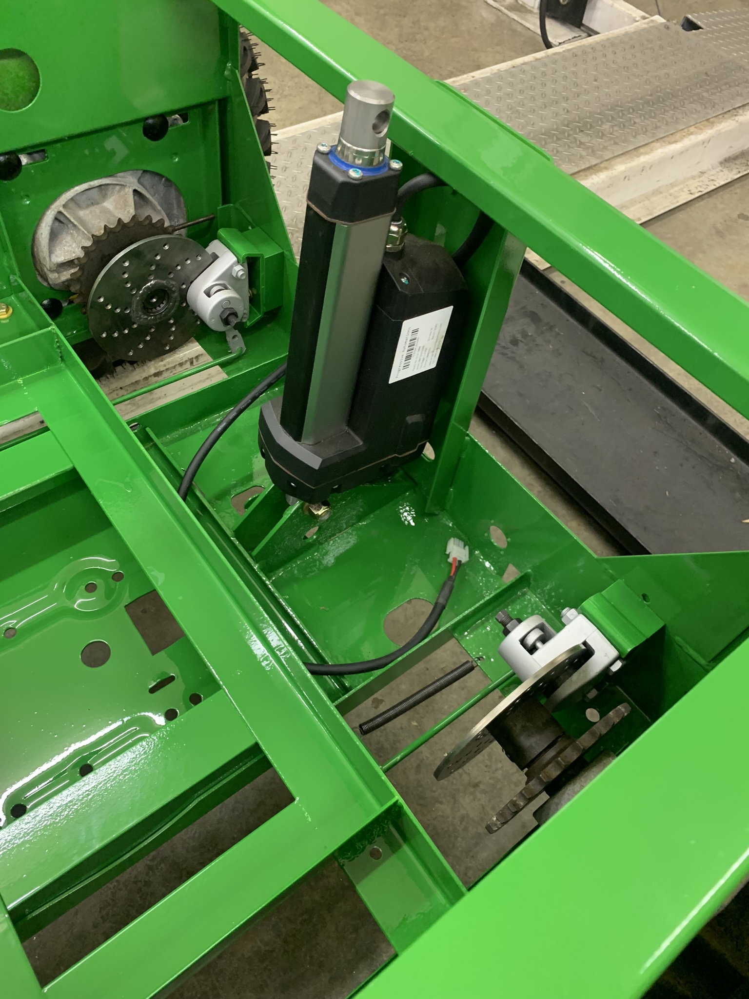
New linear actuator to lift the bed. The old one burned up, and Deere wanted a mint for the replacement, but I found another after-market one to do the job rated at 3,000 Lbs. It wasn't dirt cheap, but a couple hundred bucks less than John Deere wanted. I will need to rewire a little this ram wants the voltage reversed for up and down, the original sent a positive signal on one of two lines to indicate up and down. Easy enough to change with a DPDT switch with some crisscross jumpers between the sides. I needed to grind the lower mount a little for it to pivot, but the top bolted right in.
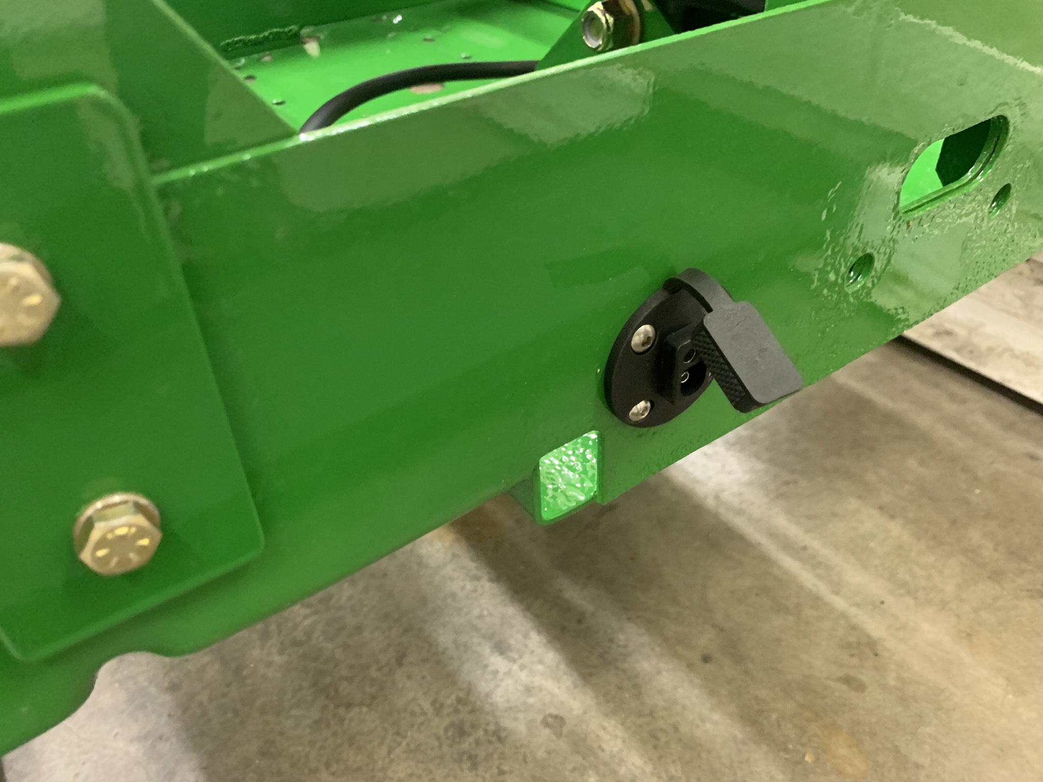
Heres a switched 12v jack I added at the back of it. It takes a flat 2-pin connector similar to the 4-pin connectors used on most small trailers. I put a switch on the dash to turn it on and off, with a light indicating its on. We use this for a sprayer.
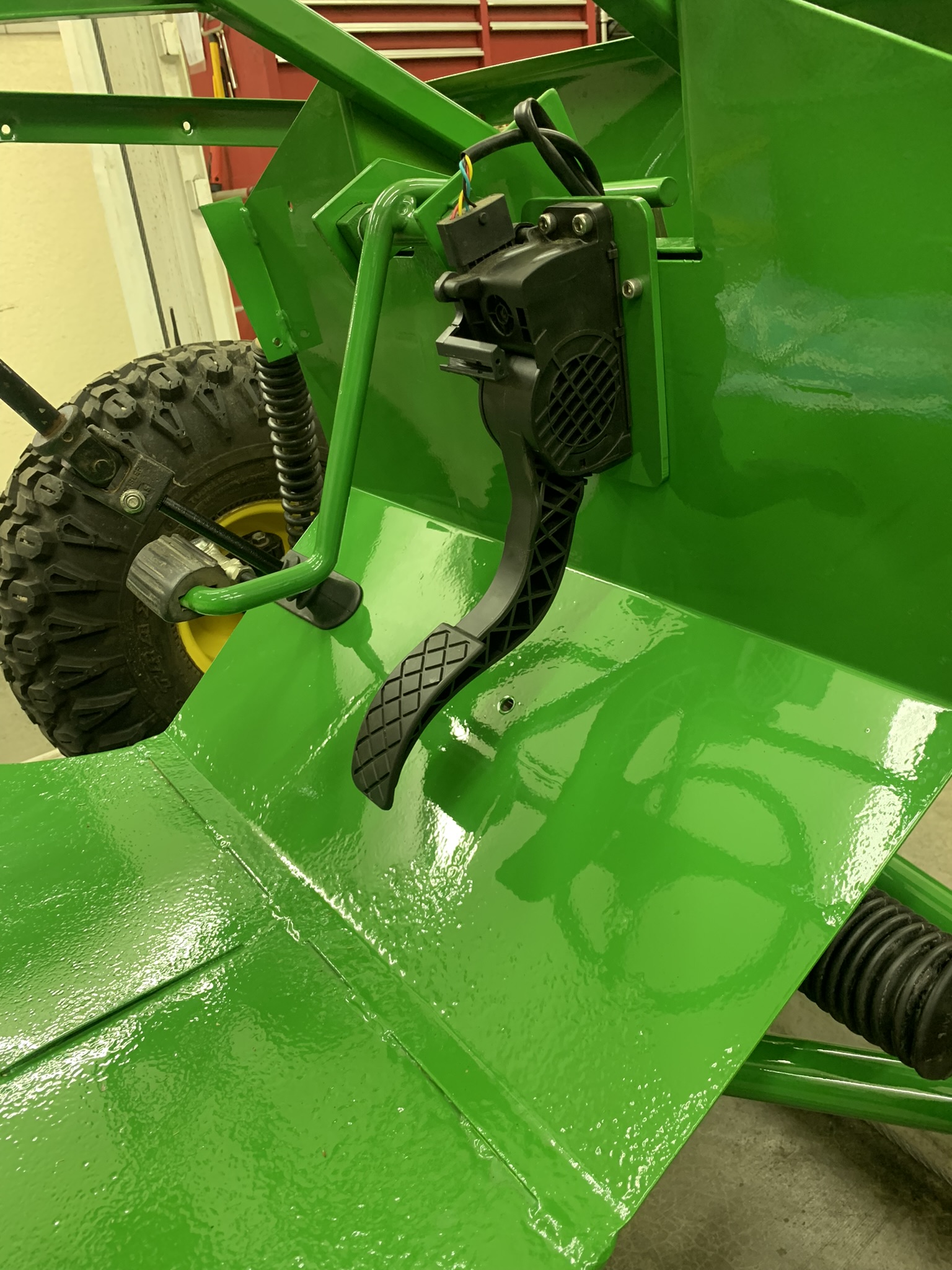
"Gas" pedal final installation.
Charger jack - Yamaha style.
Disconnect switch for batteries, near operator
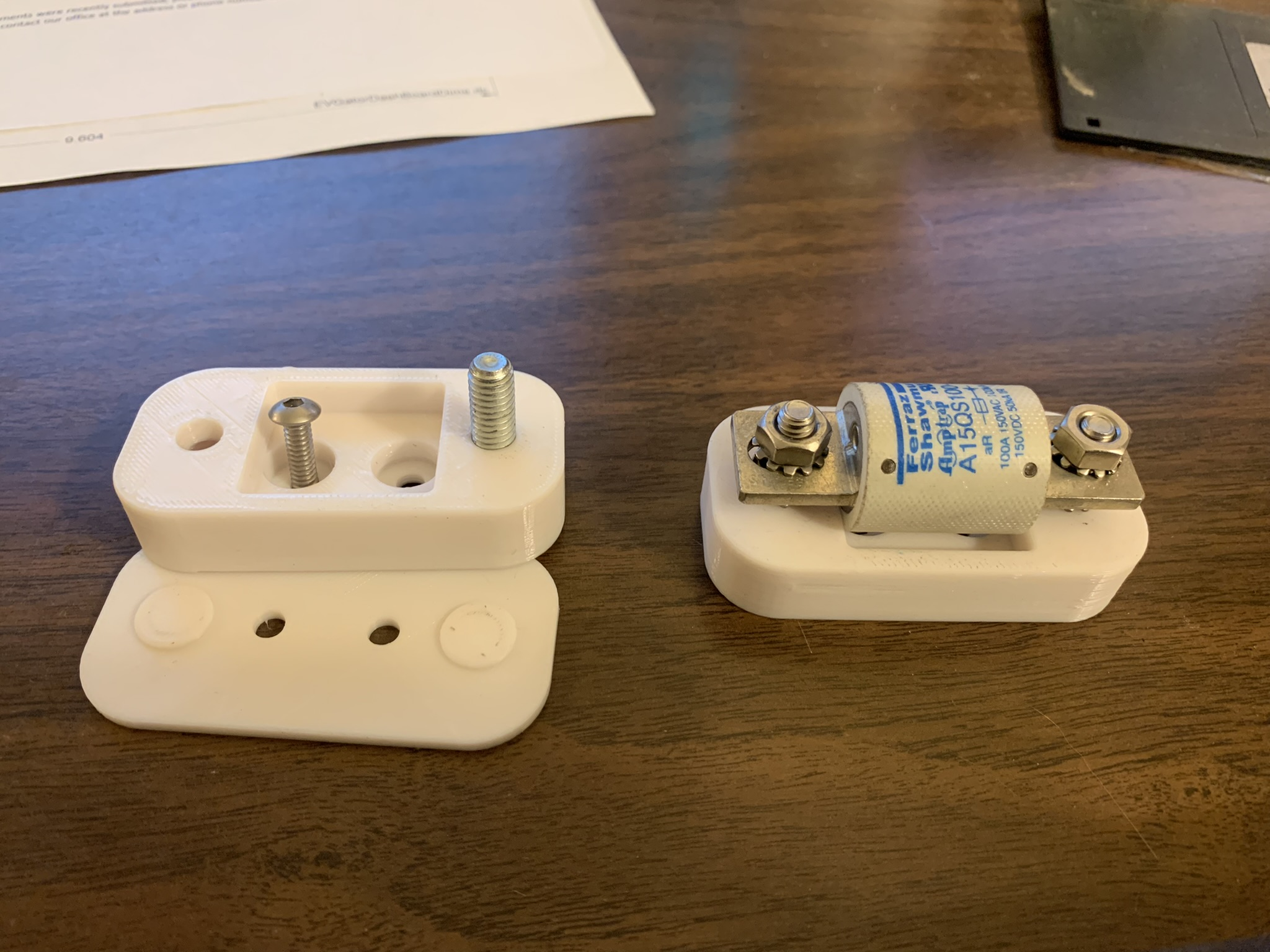
400A solid-state fuses, three places, one per battery bank.
The fuse manufacturer wanted something like $70/each for fuse mounts, instead I drew them up on CAD and 3D printed them for cheap.
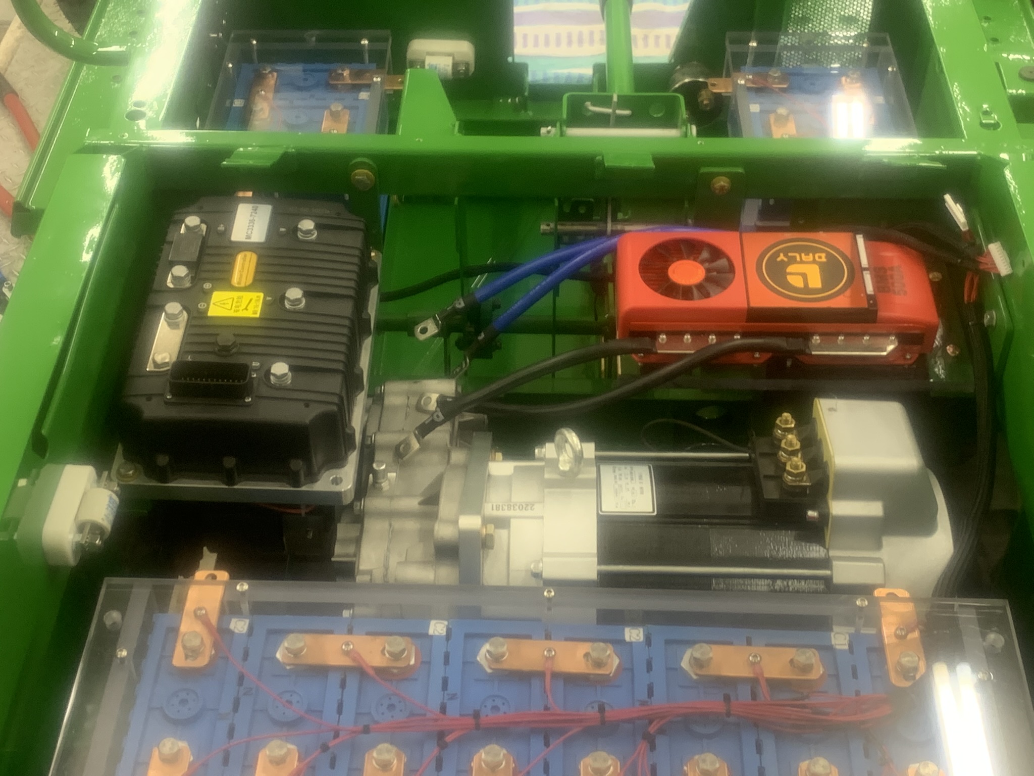
BMS Mounted and covers on batteries This red BMS has two electronic switches in parallel with a separate #2-AWG cable for each switch. Since the rest of the system is single #2-AWG wire, this parallel cable setup doesnt make sense and will be awkward to connect.
So I made a couple of bus-bars from 1 x 1/8-thick copper to replace the two cables on each side of the BMS.
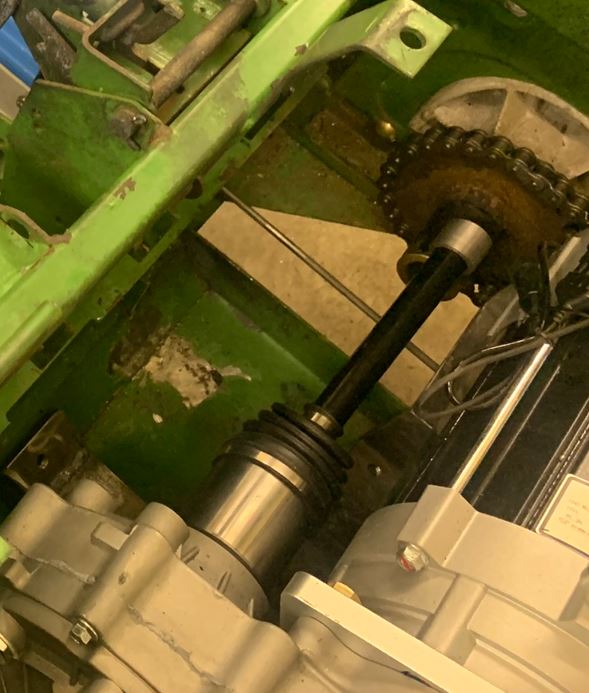
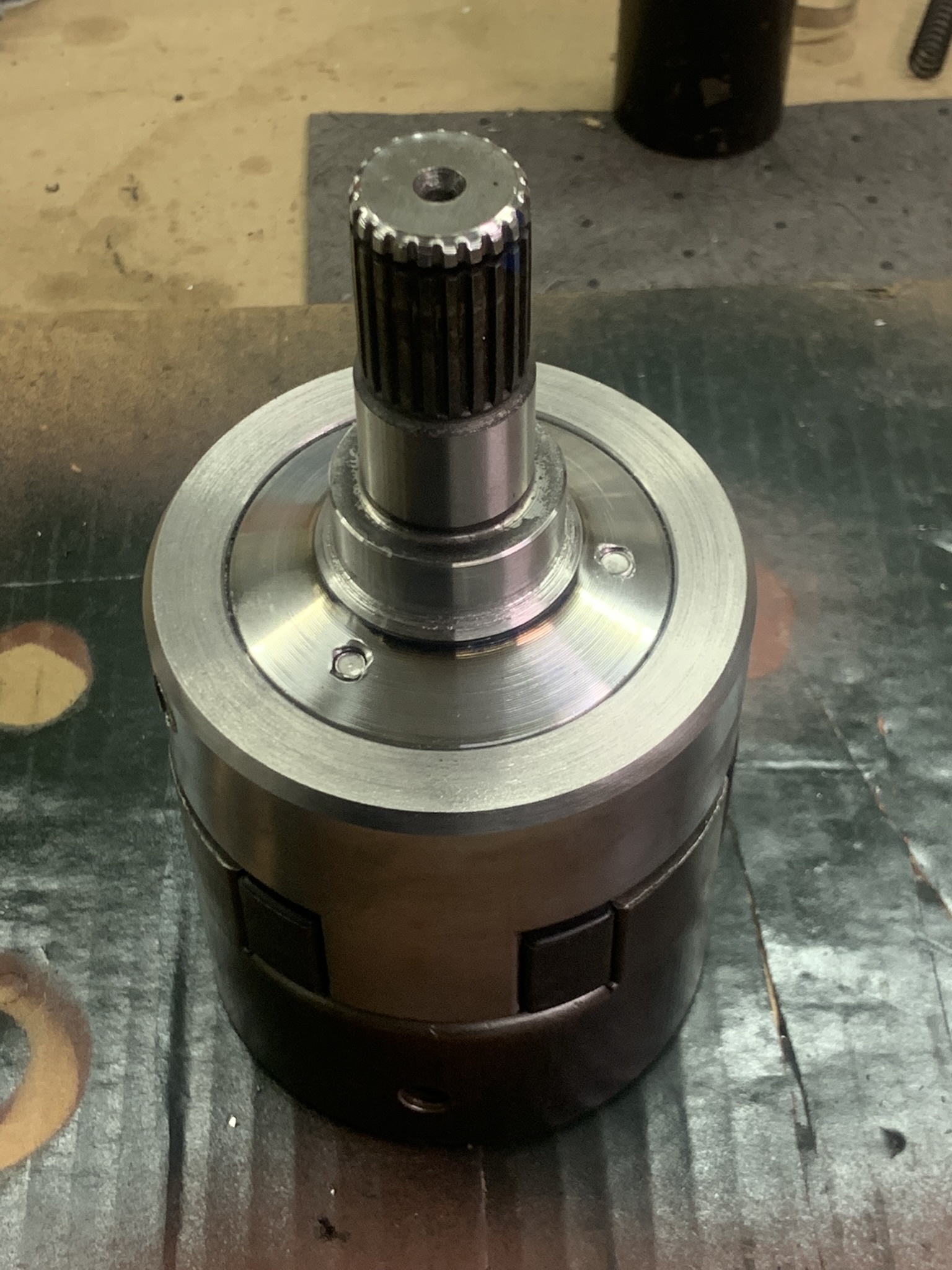
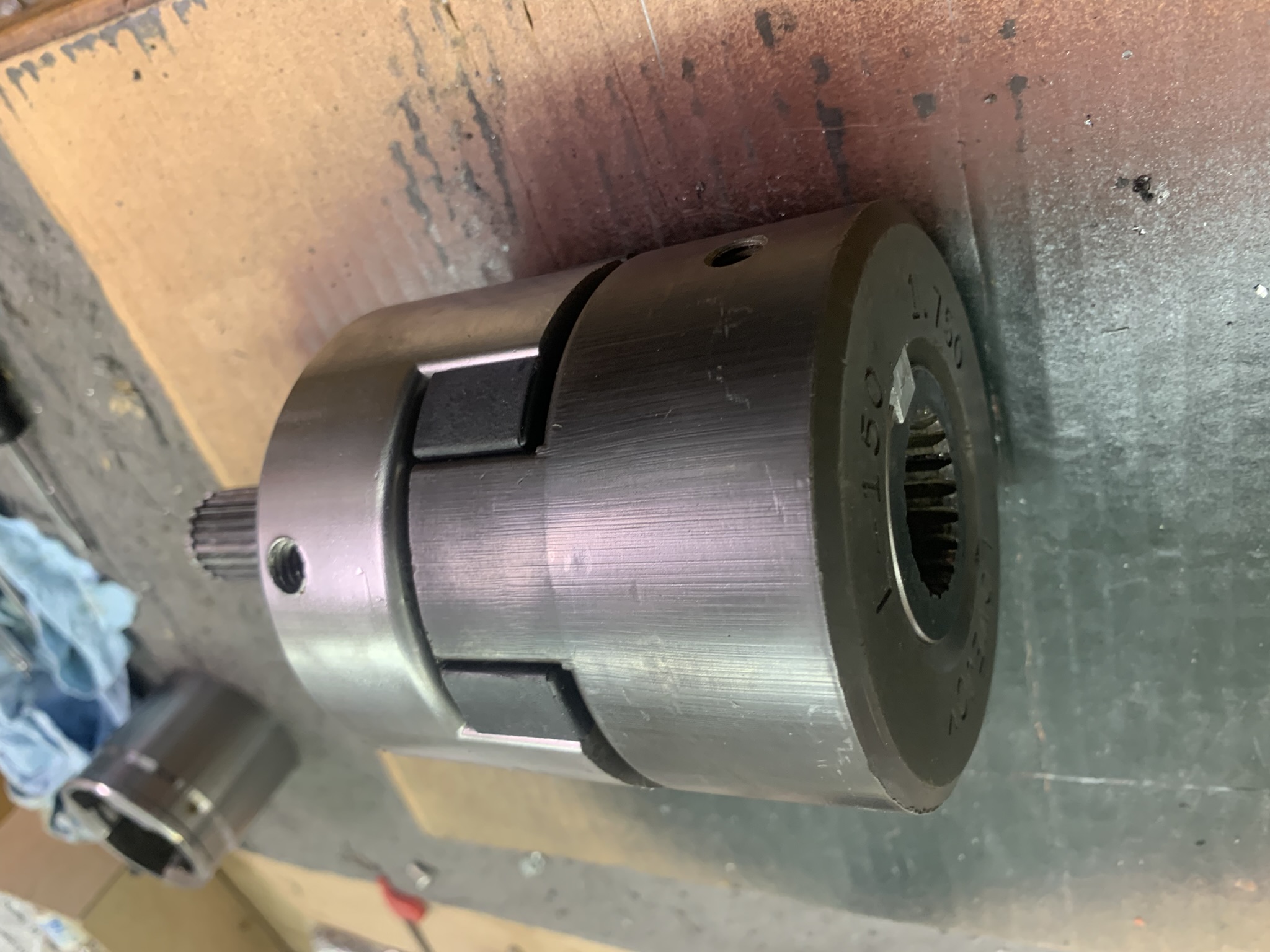
Its starting to look pretty complete. Since the coupling is so narrow on this side, the motor axle alignment needs to be near perfect. When I spun the axle with the original solution, it bound slightly during part of the revolution, so I decided to replace it with a Lovejoy coupling. This allows a small amount of lateral and axial mismatch, and also add a little cushioning to the drive. From the specifications, I figured I needed the 150-size units to deal with the electric motor torque. Lovejoy wants a lot of money for their parts, so I sourced the three parts used from various vendors on eBay. And they were surprisingly large when they arrived. I had to cut, drill and tap the CV-shell to attach it to one side, then machine the splined Deere connector to size and cut a keyway in it for that side. The next picture is the finished installation, the next two show modifications to adapt the Lovejoy at each end.
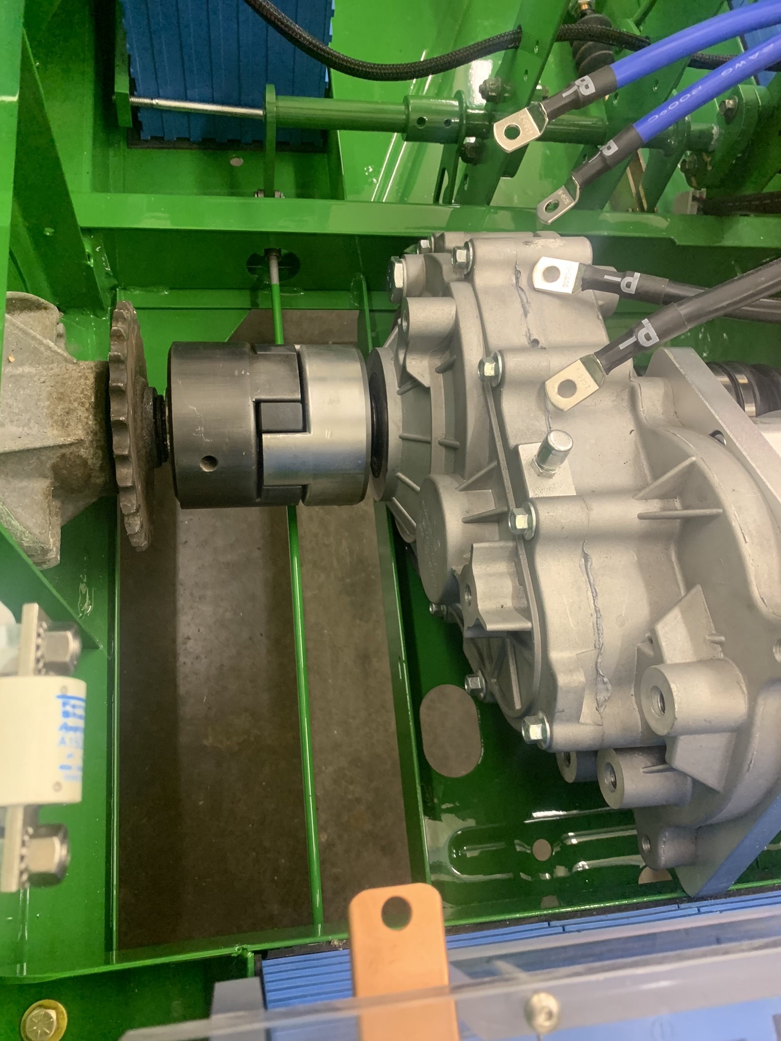
Now that this connection is complete, I can mount the controller above it, shown on the left of this shot
At last, its time to do the power wiring. I used #2-AWG wire that is made for this purpose. Its very similar to welder cable, very flexible, but has an additional shield for protection thats the white part in this picture.
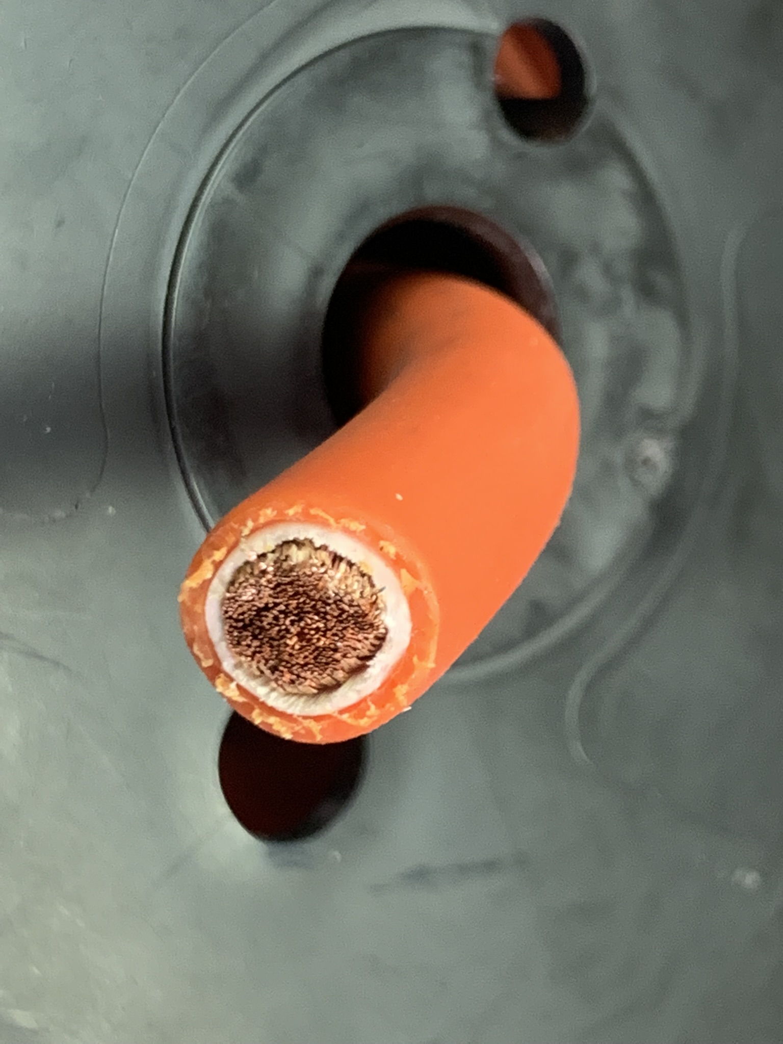
I used a crimper to install the cable ends, then put heat-shrink over that, and finally rubber boots at the end.
Here it is after putting in the big cabling. As you can see at the top of the batteries, I've also been busy extending and running all the BMS monitor wires, one to each cell.
If you're curious, this is the rear wiring diagram of the vehicle, and this is the front wiring diagram of the Gator.
I did the low-power/low-voltage wiring, and the scary moment to turn it on was here. Before I did that, I plugged a lab power supply into the 12v side of the wiring and debugged that. All seemed to work fine (lights, aux-rear power, bed raise/lower, park brake indicator), except that the aux power toggle switch works backwards. When you press the side labeled zero it turns power on, and when you turn it to the side labeled one, power is off. Guess Ill have to find another switch that is closed when the on side is pressed..
The front drive-wheels are not mounted, and the roller chains to the rear drive-wheels are not installed, so the axles can turn with the Gator going anywhere. I turned on the main power disconnect, and no smoke yeah!! Then the ignition switch, and 12v is there from the DC:DC converter. Then, I put the direction switch in forward and pressed the gas pedal. The wheels spun, but backwards! If I put it in reverse, they spin forward. I reversed the wires of the direction switch, and they started going the right direction. All looking good. The instrument cluster lights as appropriate, the fuel-level gauge seems about right, and the speedometer goes up with wheel speed.
Trouble is that it goes backwards much faster than forward. According to the speedometer (which I will likely need to calibrate to my wheel sizes), it goes about 40 km forward, and 70 km backwards. I need to figure this out I sent an inquiry to the motor manufacturer to see what they have to say. But, all in all, Im tickled that its this close on first turn-on. I want to hear back about the forward/reverse speed situation before I put on wheels and actually drive it.
The manufacturer got back to me about the speed reversal. To properly do the reversal, I needed to change the dash-panel switch back to normal, then reverse two of the three big cables going between the motor and the controller, and one more small wiring swap at the controller. Now all is good in this regard.
I finally took it out for a spin, and it sure does go! Matter of fact it's too fast - the brakes can't slow it down well enough. According to the GPS speedometer in my phone, it hits about 30 MPH. The dash cluster reads about 75 km at 20 MPH, should be about half that (32kmh). Another question off to the vendor about how to recalibrate this. It takes a fair amount of throttle to get going from a stop, but then it starts accelerating faster and faster as the speed builds.
Fast as it is, I can't really drive it with the weak brakes, so I need to redirect my attention that way. I've decided to do a couple changes. First, I'm going to change the size of the disks from 6" diameter to 8" diameter. That change by itself should increase braking power by about 40%, and I think that they will fit in there, but barely. To make really sure it will stop, I'm also going to add a hydraulic brake system, and two more calipers that share the same disks (rotors). I'll need to leave the mechanical calipers to serve as a park brake, hydraulic systems shouldn't be used in this application.
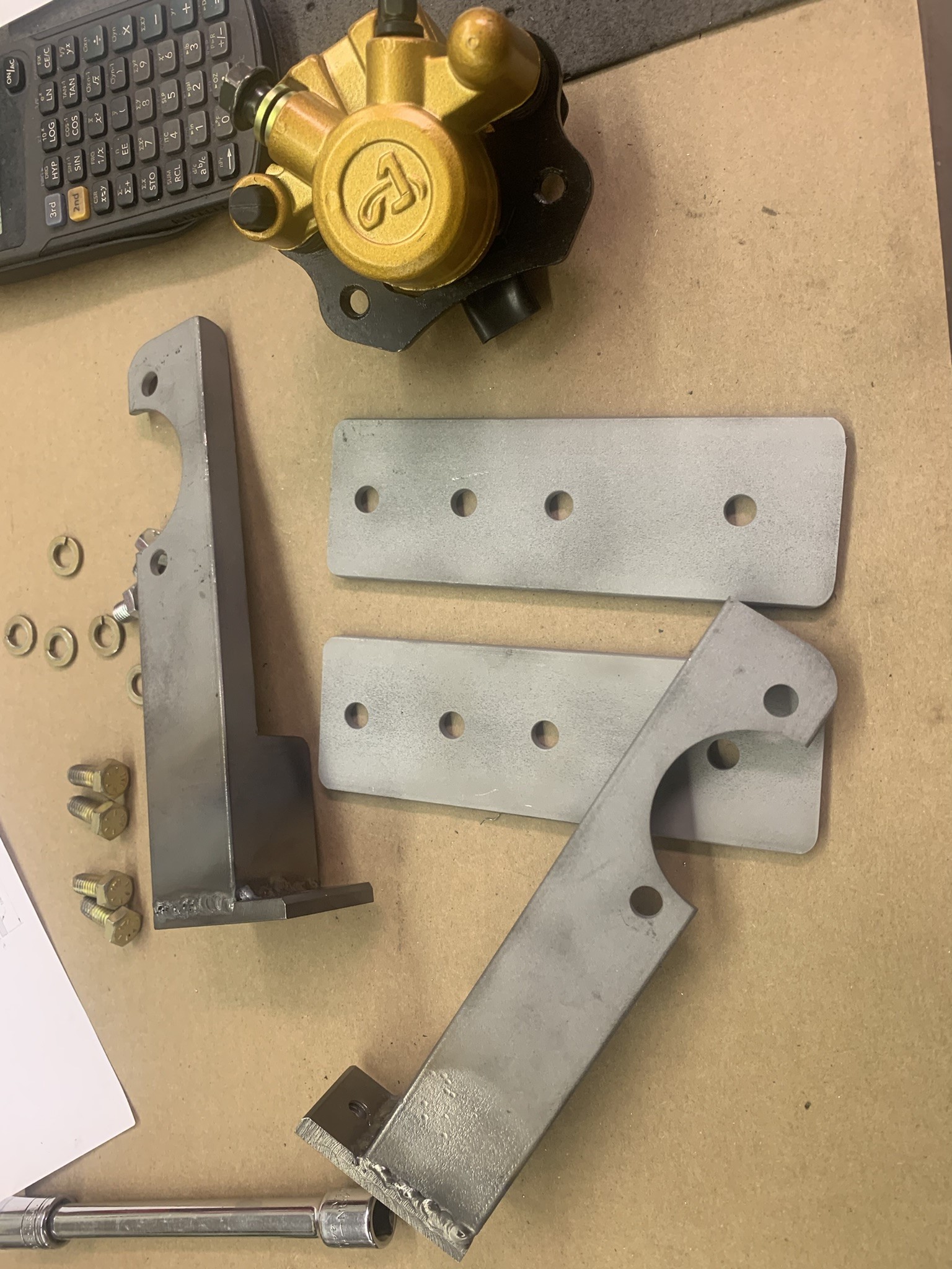
So - I found some more 3/16" steel to make the bigger disks and caliper mounts, made longer actuator rods, and added bracketry to install a master cylinder behind the dash. The calipers I used (cheap - from Amazon for about $18 each) specified a master cylinder requirement of .70" diameter when used as a pair. I happened to have a .75" Tilton cylinder in my extra parts stash, so I'll use that, and if pedal pressure is too high, change to a .625" cylinder.
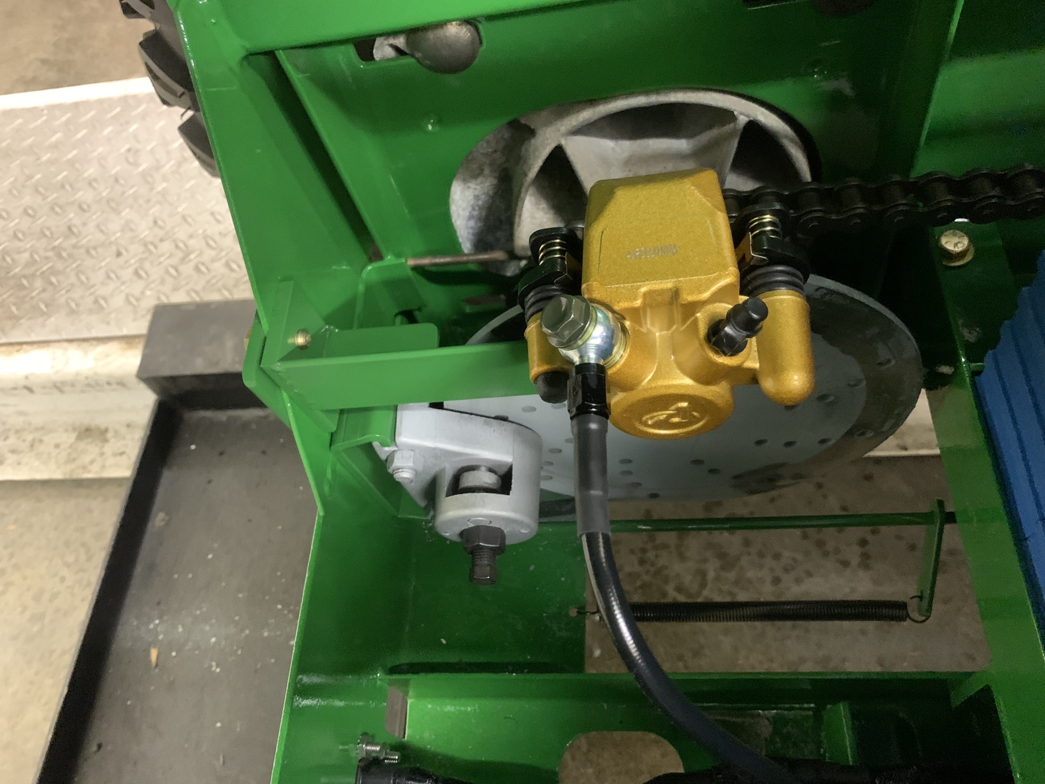
Here's the new setup. First picture shows the caliper and mounting brackets (mirror image on one of them). The next shows them installed.
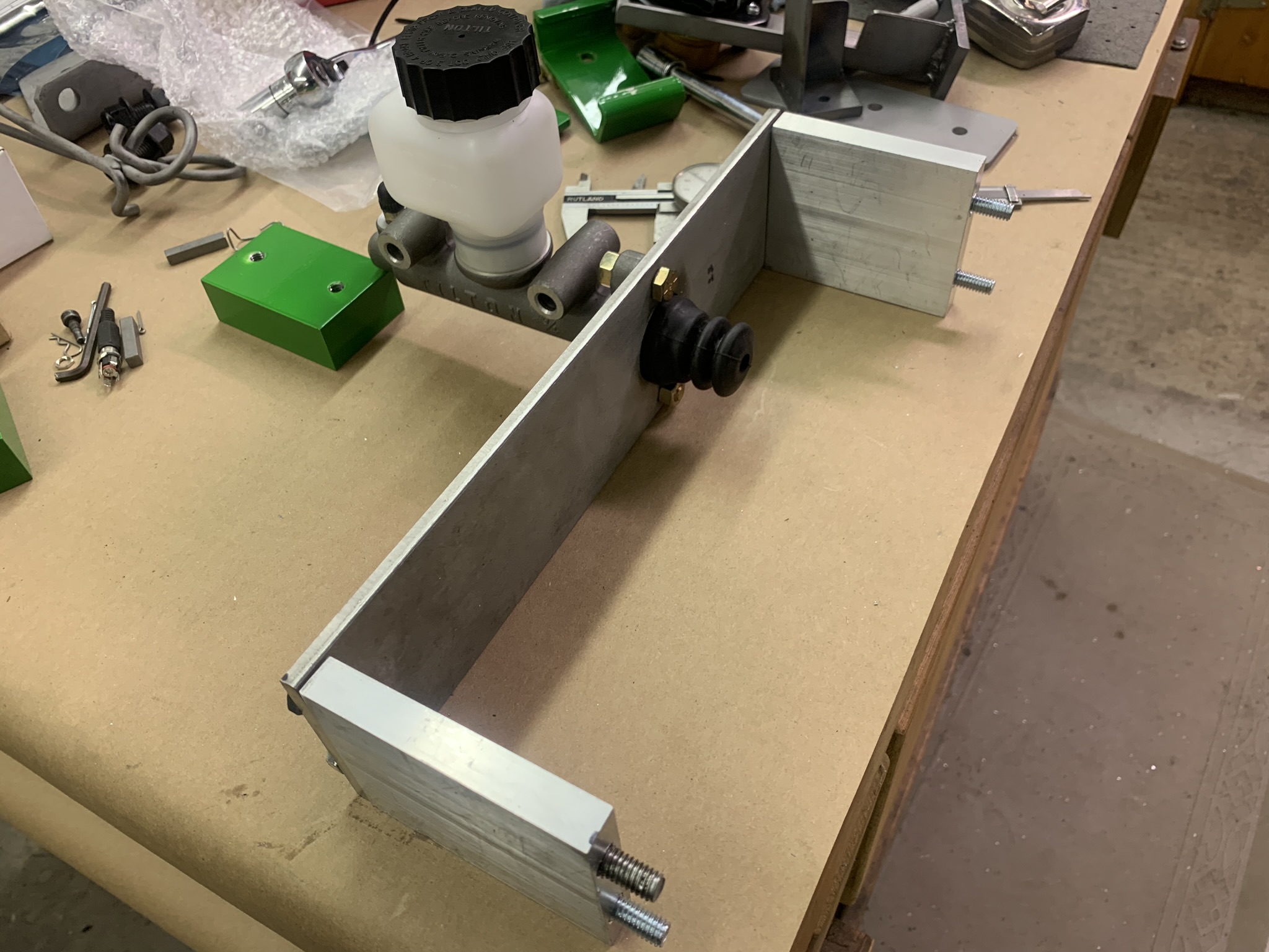
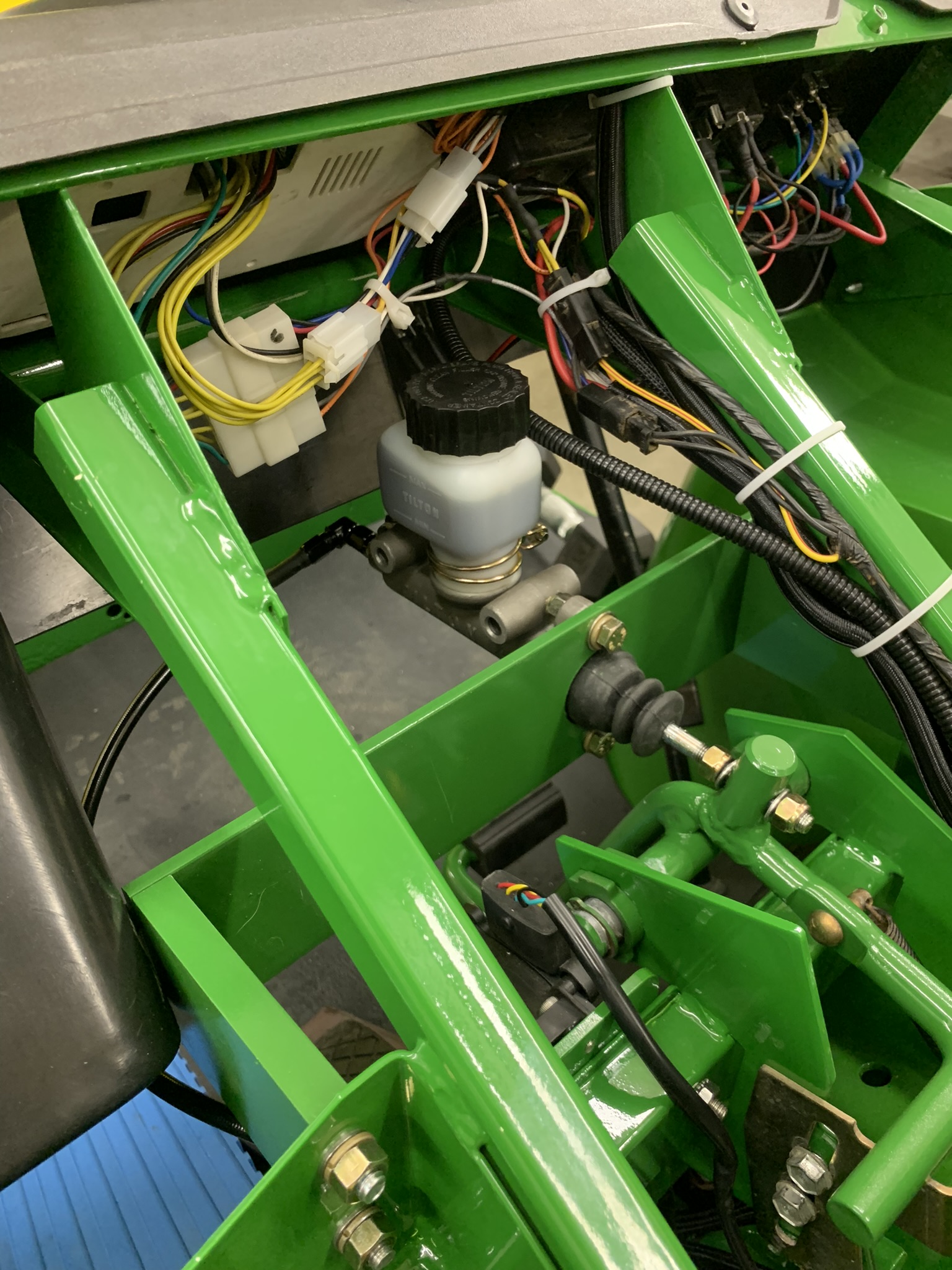
This shows the raw bracketry for the master cylinder, and then as installed. I made a post out of 3/4" steel rod, put a slot in it, and welded it to the top of the original brake pedal pedal operating lever to press on the cylinder rod. I was a little worried about the metal cylinder mounting-plate flexing, but that doesn't seem to be the case. It's 1/4" thick x 3" stainless steel.
The new improved brakes work great!
After finishing up the brakes, and removing the unneeded front brake cable, I found that there was adequate room to mount the charger on-board. This will make it so that it can be charged anywhere with a 115v extension cord. I mounted the charger on 1.5" high posts to allow better cooling, and also to allow some of the other wiring and cables to run below it.
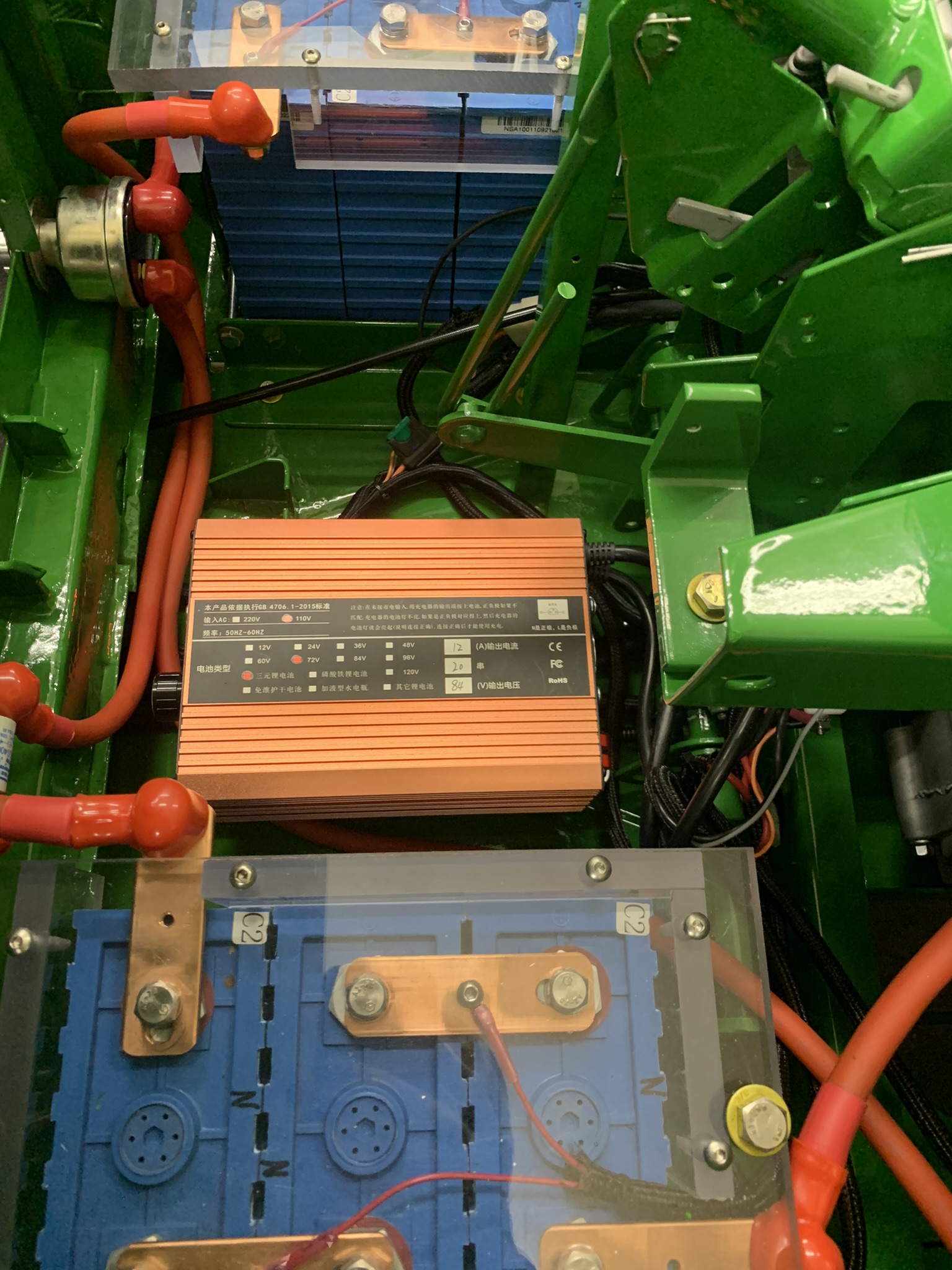
This required a new power entry panel and jack - here's the assembly:
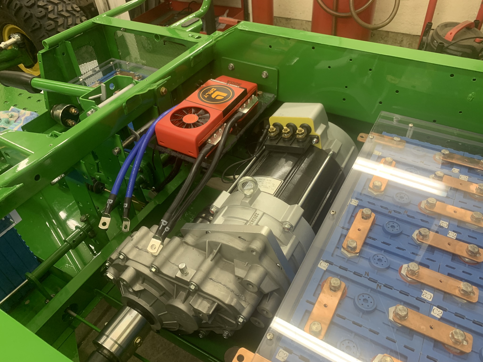
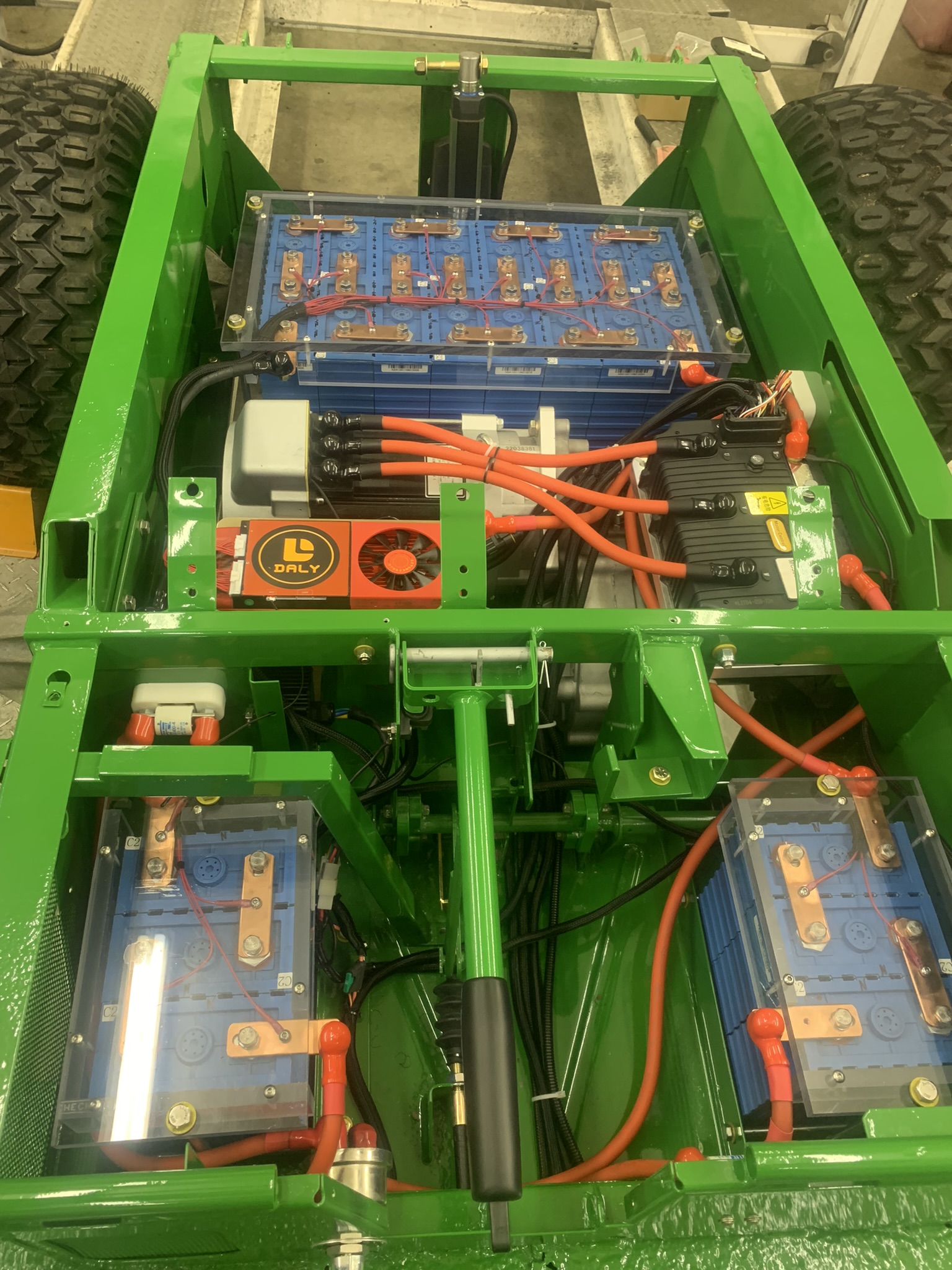
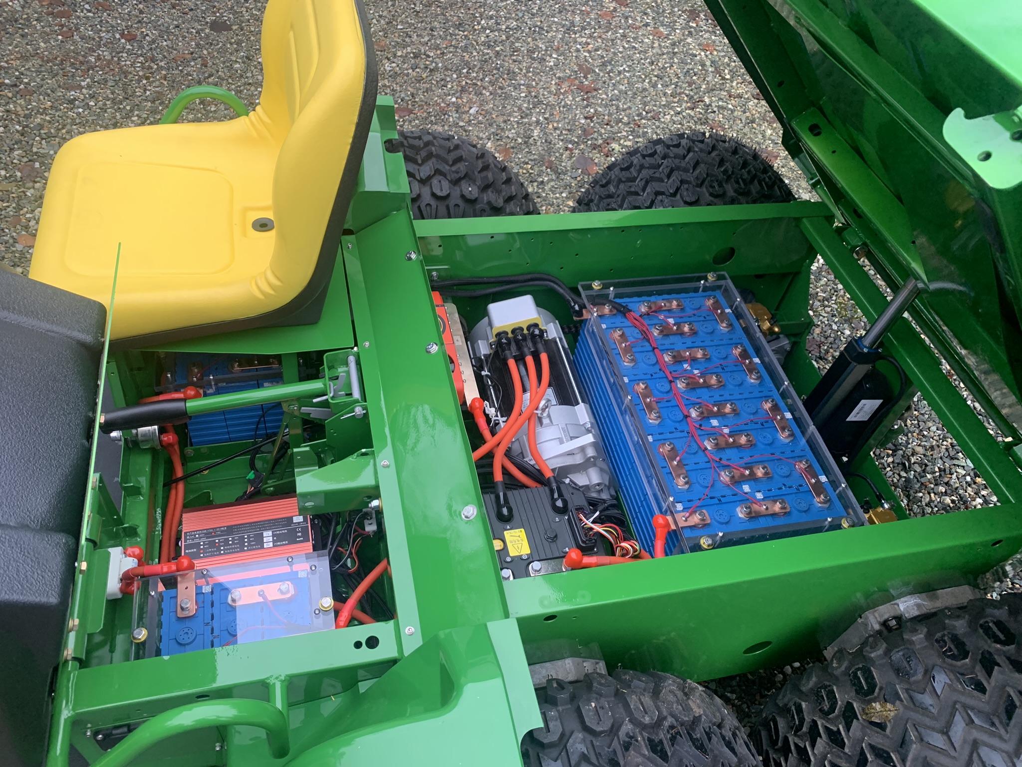
Here it is in the present condition. Everything works on it now.
And here it is with the hatches open...
I'm happy with the way this project turned out. It hums along at 30 MPH silently and has plenty of acceleration. Once it starts to get more use, I'll get some idea of the range and update this. My estimate is about three hours of run time, which is several days use in our application. If I go to a little more modern batteries, this range would double, or more. But, we'll see how far it goes as is.
Is it done? I guess that there are always things that could be done if one wanted. I just got the information from the vendor and reprogrammed the dashboard to make the speedometer read more accurately. Also, I can do a lot of tweaking of the controller attributes. You can change all sorts of characteristics (speeds, acceleration rates, initial acceleration rates,..). I was given the program to do this, just need to wire up an RS-232 link from a PC to the controller, and figure out how to use the app that has all the text in Chinese. I could also tweak the BMS settings, there's a blue-tooth interface for that, but it seems to be fine as is. Here's a video of the voltage and current during a short drive.
What would I do different? Hard to say. I'd be a little more creative in coming up with my own formula for the ingredients. I'd want to make sure that all could be properly integrated and there is sufficient documentation to do that. I probably wouldn't use the dash cluster again, instead I would use one of the small charge-level indicators. The manufacturer of the cluster suggested that I use it because it is accurate for the battery level - but after wiring it, I can see that it doesn't have information about current draw - all it knows is the motor speed and battery voltage. Some of the charge-level indicators have a shunt to measure current flow. That would be more accurate, and also fit into the dashboard better. I'd probably go for a little more gear reduction - this is 10:1, changing to something like 14:1 would probably be a little better if it's main use was in the fields.
After all this work, do I want to turn it back to the barn people for hauling horse-poop? Not yet !!!