
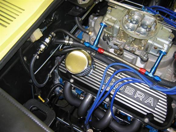
When I was prepping the engine compartment, I bent the 5/16" solid fuel line coming from the rear of the car so that it went through the corner of the tunnel (a nice big clear area) and towards the battery. Then I installed a Spectre fuel filter with a 5/16" fitting on the inlet, and a 3/8" fitting on the carb side. These fuel filters come with a variety of plastic fittings to accommodate this, but being a worrier, I went back later and changed the fittings to be bronze. Wouldn't want one to fail and spray gas all over the engine bay. That's the filter off to the left and below the electrical connector.
I had to laugh - I was explaining the problem to someone of the trouble I had encountered finding parts to adapt from 5/16" to 3/8" fuel line. He told me it probably would have worked fine to just get a standard filter with 3/8" on both sides, and just push the 5/16" on with a little force. I think he's right!
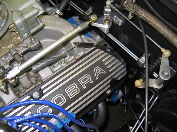
While most people use cable-type throttle linkages, I thought that it would be fun to go to a little more effort and make one without a cable. I took the original inside pivot off the dashboard and made a mount that would use the same bolt holes. Then I made a bell crank that would connect to the carburetor, and finally a shaft with Heim joints on the end for the carburetor link. Looks like the following - the link and bell crank on the right part of the linkage are original 240Z parts, and since I couldn't find a mating ball the right size I simply cut part of the old linkage off and bolted that to my new bell crank. The balls on the original linkage are not removable by mere mortals - at least not this one.
In the picture above, you can also see where I tapped into the back of the intake manifold for the power brake booster.
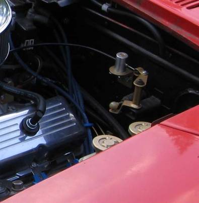
Another approach - my brother, who is a better and more creative craftsman than I, came up with a very nice cable linkage on a Z he used to have - the post that holds the cable also pivots so that there is no binding. Most folks run the cable straight out from the gas pedal, then it needs to make two bends, this implementation only requires one bend of the cable:
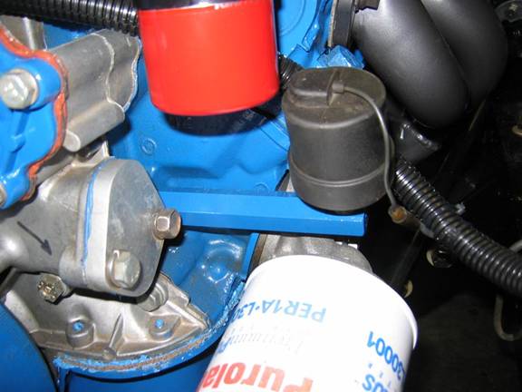
This was fairly straight forward in most cases. I found a hex-shaped oil sensor extension on a '69 Econoline van, and the Datsun sensor screwed right into it. You can see the Ford Motorsport 90-degree adapter below it. A small filter would probably work without the adapter, but it's nice to have the extra oil capacity:
Above it, I mounted the coil on the front of the cylinder head (you see the red bottom of it in the picture). Originally I used the stock Datsun mount on the wheel well, but didn't like the appearance of the extra long coil wire going to the distributor, so moved it.
The Datsun water temperature sensor screwed into a spare hole in the intake manifold right behind the water hose outlet.
Note: The threads on the sensor are metric, and the manifold is similar, but NPT threads. It works, but it's not particularly workmanlike. I discovered later, when installing the Weber manifold, that it leaked on that manifiold. I found a Ford sensor that was electrically similar, but had the correct threads. That's a better solution.
The speedometer took a little monkeying. I calculated that I would need a 21-tooth gear at the tranny, so ordered this and a cable from JTR. Unfortunately, the JTR T5 speedometer gear wasn't compatible with the Tremec, although it was a nice flexible cable (70" long) and fit the speedometer perfectly. So I ordered a Tremec gear and 65 Mustang cable from another source. This worked at the tranny just fine, but was marginally short (63") and didn't screw onto the speedometer correctly. I sent both cables to a shop in Seattle that put the Tremec end on the JTR 70" T5 cable, and it worked perfectly. They only charged twenty bucks to do the job.
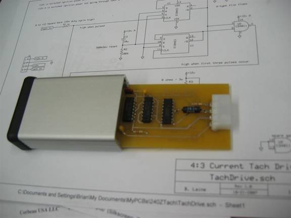
So, all the gauges worked now except the tachometer, and this was a little bit of a problem. Had I used a stock ignition system on the Ford, the tach would have worked, although it would read high since it's getting four pulses per revolution, while the tach is expecting three. The tach on the early Z's are driven by current pulses rather than voltage pulses, so the tach output of the MSD 6 wouldn't work either, and MSD tells you not to connect anything to the coil since the signals are so strong and long. Even if you could use it, the speed calibration would still be wrong. According to JTR, you can take out the tach, and tweak a calibration adjustment almost to its extreme to calibrate it. So if I had a stock ignition (providing current pulses) I could have done that, although the idea of tweaking the tach didn't particularly appeal to me.
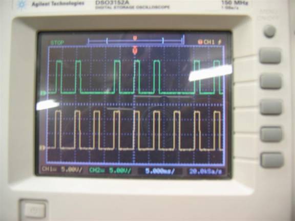
I figured that what I needed was a box that would take the tach voltage signal from the MSD 6, rescale the output 4:3, and then convert the voltage signal to a current signal. So I decided to design one. I made a circuit that eliminated each fourth pulse. Here's what it looks like on an oscilloscope, the bottom is the tach signal from the MSD box, and the top is the output signal that is subsequently converted to a current pulse:
>
I figured that this technique would work accurately with no tweaking of the tach.
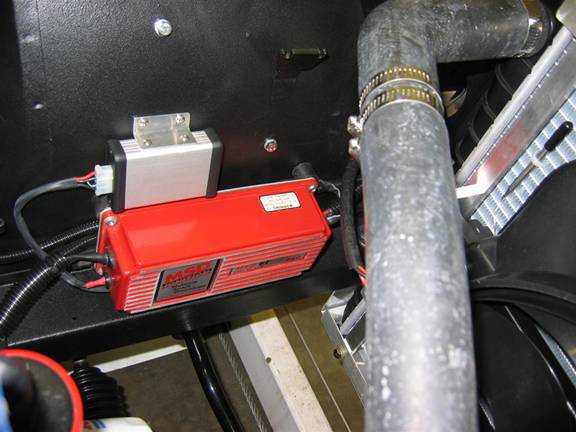
So I made the circuit and mounted it near the MSD:
>
So the final gauge, the tach, now works. It's not perfect though. It reads correctly except it tends to fluctuate a couple of hundred RPM at steady low revs. It must be from the way the tach processes the pulses. If I get ambitious later on, I might try to redesign my box so that it generates a frequency ratio of pulses that is 4:3, rather than getting rid of each fourth pulse. It's usable as is though.
Note: I did decide to go back later and revisit the tach interface. I designed something more sophisticated and general purpose. For example, you can set a switch for different combinations of engines and tachometers. Since electronics projects like this are kind of hard to implement without the correct tools, I decided to make it available as a completed module. If you are interested in learning more about it, see this:
The fuel gauge that I remounted in the fuel tank works fine. While we're discussing fuel system wiring, you will find an additional connector at the rear of the car that is designed for running an electric fuel pump in the JDM models of the 240Z. However, it isn't connected at the far end of the wire. I found the wire behind the radio, it's an unconnected 2-pin connector. I connected the green wire of these two (the other is ground) to a green wire on a nearby 8-pin connector, and that solved the problem. The middle fuse on the left row (20A) now protects the fuel pump.
We're getting close now!
The last issue under the hood was the air filter. There were two problems:(1) a high rise manifold, and (2) a large-diameter MSD distributor. If you had a normal distributor and intake manifold, I think you could throw on any standard 14" air filter. But, this is hot-rodding, and you do what you want. If it takes a little longer to do it, but you end up with something you like to look at, what the heck?
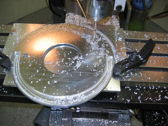
So I decided to make a 13" air filter that was slightly dropped. This would lower it slightly and the smaller diameter would miss the oversized MSD distributor.I had a K&N 2 ¼" high filter element, so I chopped a couple inches out of its circumference, and decided to take some 3/8" thick aluminum plate to make the top and bottom plates. The problem was that even though I have this neat mill that is CNC in two axes, it only has 12 inches of travel in the Y direction. So it was a matter of making a tooling plate to hold down the plates, zero it, machine one half of one side, spin it, rezero, do the other edge, flop it over, etc. And since it doesn't have flood cooling (it has mist), I had to run the drive speed really slow since if it ever gummed up, you're back to base zero and need to start over again. So lots of hours sitting there watching it work, listening for problems, moving and rezeroing, etc. I know, life is tough!
Here it is in the making…
And this is it all done…
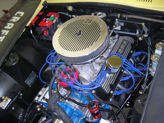
My thanks to my brother for suggesting the air filter styling to match the valve covers, and my son's suggestion for the Z8 moniker. And while BMW has a Z8 too, this is really a "Z".